

Table of Contents
- Bently Nevada 162381-064-028-50-05 Probe Installation Guide Entry
- 3300 XL 8 mm Probe Role in Vibration Monitoring System
- Pre-Installation Checks and Risk Identification
- Probe Mounting Strategy and Gap Control
- System Configuration and Signal Setup
- Commissioning and Gap Voltage Validation
- FAQ
- Technical Summary
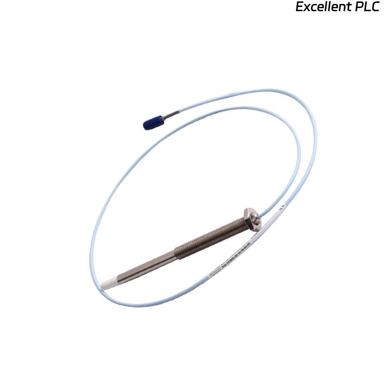
Bently Nevada 162381-064-028-50-05 Probe Installation Guide Entry
Bently Nevada 162381-064-028-50-05 3300 XL 8 mm proximity probe installation errors typically result in incorrect gap voltage and unreliable vibration data due to improper mechanical positioning rather than probe defects.
This Installation Guide explains how to achieve accurate probe installation, correct gap setting, and stable system configuration.
3300 XL 8 mm Probe Role in Vibration Monitoring System
- Measures shaft displacement and vibration in rotating machinery
- Provides high-resolution signal for condition monitoring
- Works with extension cable and proximitor module
Accurate installation directly impacts measurement reliability.
Pre-Installation Checks and Risk Identification
- Verify probe length and thread compatibility
- Inspect probe tip for physical damage
- Check mounting bracket alignment
- Ensure target surface is clean and conductive
Field Insight: Surface contamination can significantly affect signal accuracy.
Probe Mounting Strategy and Gap Control
- Install probe into mounting hole with proper alignment
- Adjust probe position to achieve initial gap
- Secure probe using locknut without shifting position
- Avoid contact between probe tip and shaft
Gap control is the most critical step in installation.
System Configuration and Signal Setup
- Connect probe to extension cable and proximitor
- Verify system compatibility (3300 XL series)
- Ensure proper grounding and shielding
IF no signal:
    check cable connections
    verify proximitor power

IF unstable voltage:
    inspect probe mounting
    check gap alignment

IF signal drift:
    inspect environmental conditions
    verify grounding
Real Case:
In a steam turbine installation, initial gap voltage measured -6V, outside the optimal range. After adjusting probe position, voltage stabilized at -9V, and vibration readings became consistent.
Commissioning and Gap Voltage Validation
- Measure output voltage (target typically -8V to -10V)
- Verify signal stability under running conditions
- Confirm calibration with monitoring system
Correct commissioning ensures long-term measurement accuracy.
FAQ
What is the ideal gap voltage for 3300 XL probes?
Typically between -8V and -10V for optimal performance.
Can improper mounting affect vibration readings?
Yes, incorrect positioning leads to inaccurate measurements.
Why is surface condition important?
Contamination or uneven surfaces can distort the sensor signal.
Technical Summary
This Installation Guide highlights that Bently Nevada 162381-064-028-50-05 proximity probe performance depends on precise gap control, correct mounting, and proper system configuration. Accurate installation ensures reliable vibration monitoring in critical machinery.