

Table of Contents
- Bently Nevada 162381-078-027-50-05 Probe Installation Guide Entry
- 3300 XL 8 mm Probe Function in Monitoring System
- Environmental and Mechanical Preparation Strategy
- Probe Alignment and Mechanical Installation Method
- Wiring and System Configuration
- Commissioning and Signal Verification
- FAQ
- Technical Summary
Bently Nevada 162381-078-027-50-05 Probe Installation Guide Entry
Bently Nevada 162381-078-027-50-05 3300 XL 8 mm proximity probe installation problems frequently result in signal non-linearity and unstable readings due to poor alignment or incorrect gap setting rather than sensor defects.
This Installation Guide focuses on engineering-based installation techniques to ensure stable measurement performance.
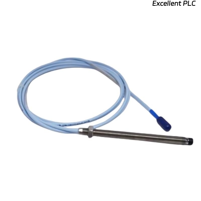
3300 XL 8 mm Probe Function in Monitoring System
- Measures radial shaft vibration and displacement
- Provides analog signal for machinery protection systems
- Works with extension cable and proximitor module as a system
Probe accuracy depends heavily on installation precision.
Environmental and Mechanical Preparation Strategy
- Ensure rigid mounting bracket to minimize mechanical resonance
- Avoid installing near strong electromagnetic sources
- Verify shaft surface material compatibility (conductive metal)
- Check installation space for proper probe positioning
Field Observation: In high-temperature zones, thermal expansion can shift probe alignment over time.
Probe Alignment and Mechanical Installation Method
- Insert probe into threaded mounting hole
- Adjust probe tip toward shaft centerline
- Set preliminary gap before tightening
- Lock probe position using locknut without introducing misalignment
Alignment accuracy directly affects signal linearity and repeatability.
Wiring and System Configuration
- Connect probe to compatible 3300 XL extension cable
- Link to proximitor module for signal conditioning
- Ensure proper grounding to avoid noise interference
IF signal noisy:
    check grounding quality
    inspect cable routing

IF no output:
    verify proximitor power supply
    check connector continuity

IF abnormal voltage:
    recheck probe alignment and gap
Real Case:
During a compressor commissioning, vibration readings showed irregular spikes. Investigation revealed probe misalignment by approximately 0.5 mm. After realignment and tightening, signal stabilized and peak vibration reduced from 11 mm/s to 4 mm/s.
Commissioning and Signal Verification
- Measure static gap voltage (target: -8V to -10V)
- Verify signal consistency during machine startup
- Compare readings with baseline vibration data
Verification ensures correct installation and system readiness.
FAQ
Why is probe alignment critical?
Misalignment causes signal distortion and inaccurate vibration measurement.
What happens if the probe is too close to the shaft?
It may produce excessive voltage and risk physical contact.
Can environmental factors affect probe performance?
Yes, temperature and vibration can influence probe stability.
Technical Summary
This Installation Guide demonstrates that Bently Nevada 162381-078-027-50-05 probe performance relies on precise alignment, correct gap setting, and proper system configuration. Engineering-focused installation ensures accurate and reliable vibration monitoring.