

Table of Contents
- Bently Nevada 162381-138-040-90-05 Installation Guide Entry
- Probe Role in Long System Configuration
- Installation Risk Factors for Extended Length Probes
- Mechanical Installation and Gap Control Methodology
- System Integration and Signal Path Setup
- Commissioning Strategy and Signal Validation
- FAQ
- Technical Summary
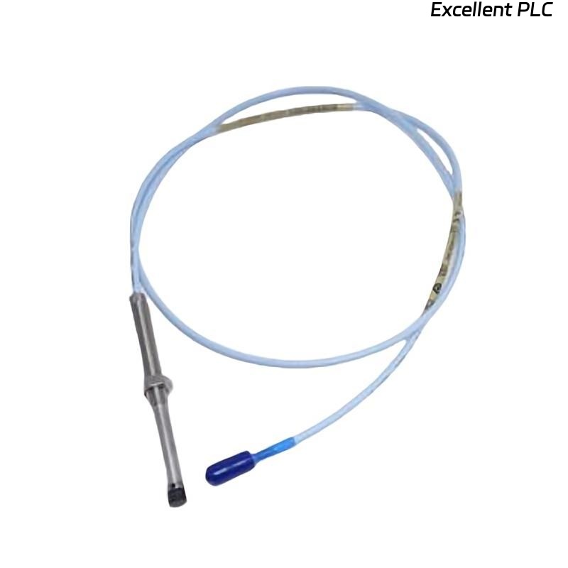
Bently Nevada 162381-138-040-90-05 Installation Guide Entry
Bently Nevada 162381-138-040-90-05 3300 XL 8 mm proximity probe installation challenges are commonly linked to signal attenuation and mechanical instability due to extended probe length rather than sensor malfunction.
This Installation Guide focuses on ensuring stable signal transmission and precise gap control in long cable configurations.
Probe Role in Long System Configuration
- Designed for extended reach installations in large machinery
- Measures shaft displacement in difficult-to-access locations
- Works as part of a calibrated system (probe + extension cable + proximitor)
System integrity becomes more critical as length increases.
Installation Risk Factors for Extended Length Probes
- Signal degradation due to longer transmission path
- Mechanical vibration affecting probe stability
- Increased susceptibility to electromagnetic interference
- Improper cable routing causing noise pickup
Engineering Insight: Long probe assemblies require stricter installation discipline compared to standard lengths.
Mechanical Installation and Gap Control Methodology
- Install probe into mounting port ensuring axial alignment
- Set initial probe gap manually before tightening
- Use locking mechanism to prevent drift during operation
- Provide mechanical support to avoid vibration-induced movement
Gap stability is more difficult to maintain in long probe setups.
System Integration and Signal Path Setup
- Ensure total system length matches proximitor calibration
- Verify proper cable shielding continuity
- Maintain correct grounding across entire signal path
IF signal weak:
    check total system length
    verify cable matching

IF noisy signal:
    inspect grounding
    review cable routing

IF unstable output:
    check probe mechanical fixation
    inspect vibration influence
Real Case:
In a large turbine installation, extended probe configuration showed noisy vibration signals. Analysis found improper cable routing near power lines. After rerouting and improving grounding, signal noise reduced significantly and vibration stabilized from ±2 mm fluctuation to less than ±0.5 mm.
Commissioning Strategy and Signal Validation
- Verify static gap voltage (-8V to -10V)
- Measure signal stability under load conditions
- Compare signal quality against baseline data
Commissioning ensures that installation meets measurement requirements.
FAQ
Why are long probes more sensitive to noise?
Longer signal paths increase susceptibility to electromagnetic interference.
Can incorrect system length affect measurement?
Yes, mismatched length disrupts calibration and signal accuracy.
How to stabilize long probe installations?
Ensure proper mechanical support and optimized cable routing.
Technical Summary
This Installation Guide demonstrates that Bently Nevada 162381-138-040-90-05 probe installation requires careful control of system length, grounding, and mechanical stability. Proper setup ensures accurate vibration monitoring in extended configurations.