

Table of Contents
- Bently Nevada 164517-025-10-02-00 Installation Guide Entry
- Probe Application in Ceramic Tip Reverse Mount Systems
- Mechanical and Thermal Risk Considerations
- Reverse Mount Installation Process and Gap Setting
- Signal Chain Setup and System Configuration
- Commissioning Under High-Temperature Conditions
- FAQ
- Technical Summary
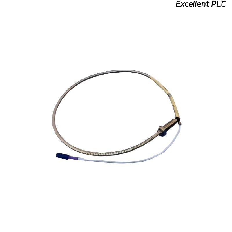
Bently Nevada 164517-025-10-02-00 Installation Guide Entry
Bently Nevada 164517-025-10-02-00 3300 ceramic tip proximity probe installation failures are often caused by improper reverse mounting alignment and thermal expansion effects rather than probe damage.
This Installation Guide focuses on correct reverse mounting techniques and maintaining stable gap under high-temperature conditions.
Probe Application in Ceramic Tip Reverse Mount Systems
- Designed for high-temperature environments
- Ceramic tip provides thermal resistance and insulation
- Commonly used in turbines and compressors
- Supports reverse mounting configurations
Correct installation is critical due to thermal and mechanical stresses.
Mechanical and Thermal Risk Considerations
- Thermal expansion altering probe gap during operation
- Mechanical stress on ceramic tip during installation
- Misalignment due to reverse mounting geometry
- Vibration affecting long-term stability
Field Insight: Ceramic probes require more careful handling compared to standard probes.
Reverse Mount Installation Process and Gap Setting
- Install probe from reverse side of mounting bracket
- Align probe tip precisely with target surface
- Set cold gap considering thermal expansion offset
- Secure probe using locknut without over-tightening
Gap must be adjusted based on operating temperature, not just ambient conditions.
Signal Chain Setup and System Configuration
- Connect probe to compatible 3300 system extension cable
- Ensure proper proximitor module configuration
- Maintain shielding continuity across entire system
IF signal unstable after startup:
    check thermal expansion impact
    re-evaluate gap setting

IF no signal:
    verify connection chain
    check proximitor module

IF signal drift:
    inspect mounting rigidity
    check environmental temperature variation
Real Case:
In a gas turbine system, vibration readings increased after startup. Cold gap was set at -9V, but shifted to -6V during operation. After adjusting installation gap to compensate for thermal expansion, operating voltage stabilized at -9V and readings normalized.
Commissioning Under High-Temperature Conditions
- Measure gap voltage at operating temperature
- Monitor signal stability during load changes
- Verify consistency with baseline vibration data
Commissioning must reflect real operating conditions.
FAQ
Why is gap different between cold and hot conditions?
Thermal expansion changes the distance between probe and target.
Can ceramic tip probes be damaged during installation?
Yes, improper handling or over-tightening can damage the ceramic tip.
How to determine correct installation gap?
Set gap based on expected operating temperature conditions.
Technical Summary
This Installation Guide highlights that Bently Nevada 164517-025-10-02-00 probe installation requires careful reverse mounting, thermal compensation, and precise system configuration. Proper setup ensures reliable performance in high-temperature environments.