

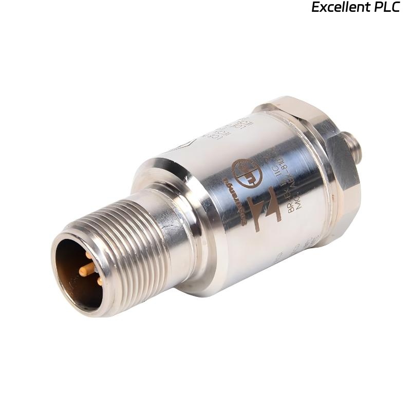
The Bently Nevada 330400-00-00 accelerometer plays a vital role in machinery condition monitoring by transmitting high-frequency vibration signals to protection systems such as the 3500 Machinery Protection System. One common failure mode encountered in industrial environments is signal loss caused by cable damage. This document explains how cable damage occurs, how to diagnose it, and how to restore system function.
1. Common Industrial Scenario
In rotating equipment applications—including turbines, pumps, compressors, and blowers—the accelerometer cable is exposed to:
-
Severe vibration
-
Oil, grease, chemicals
-
Heat from nearby machinery
-
Mechanical abrasion and impacts
-
Cable bending and flexing during maintenance
As a result, the cable becomes a critical failure point.
2. Symptoms Indicating Cable-Related Signal Loss
The following symptoms are typically observed in monitoring software or protection modules:
✔ No vibration waveform at all (flatlined signal)
✔ Abnormally low amplitude on FFT spectrum
✔ Intermittent signal dropouts during machine operation
✔ 3500 module displaying “Channel Not OK” or “Input Open” status
✔ Sudden loss of Keyphasor®-correlated peaks
✔ False zero-vibration conditions despite machine running
In some cases, the problem appears intermittently before progressing to complete failure.
3. Cable Failure Root Causes
Field inspections identified several recurring causes:
A. Mechanical Abrasion
-
Cable rubbing against metal conduit or sharp edges
-
Damaged shielding and exposed conductors
-
Oil-soaked insulation leading to cracking over time
B. Excessive Bending or Flexing
-
Frequent cable movement due to maintenance operations
-
Incorrect bend radius near sensor or junction box
C. Chemical Exposure
-
Oil and solvent attack on cable jacket
-
Acidic vapors in chemical plants accelerating insulation decay
D. Thermal Stress
-
Cable routed near steam lines or high-temperature surfaces
-
Heat-induced embrittlement of insulation
E. Incorrect Routing & Clamping
-
Unsupported cable vibrating freely
-
Cable acting as a “whip” under machine harmonics
These conditions eventually lead to conductor breakage or shield discontinuity.
4. Diagnostic Procedures for Field Engineers
Step 1: Visual Inspection
Check for:
-
Cuts, abrasions, melted insulation
-
Loose connectors at sensor or terminal block
-
Oil-soaked areas or swollen insulation
Step 2: Signal Verification
Use oscilloscope or portable data collector:
-
Confirm zero-signal or intermittent waveform
-
Check for high noise floor indicating shield faults
Step 3: Continuity & Resistance Tests
Using a multimeter or TDR (Time Domain Reflectometer):
-
Verify conductor continuity
-
Confirm shielding continuity end-to-end
-
Identify cable breaks at distance points (via TDR)
Step 4: Swap Test
Temporarily swap channel input:
-
If signal recovers, original cable is confirmed faulty
-
If still dead, sensor or input module should be inspected
Step 5: Module & Grounding Check
Confirm no grounding or module-side issues to avoid misdiagnosis.
5. Corrective Actions
Once cable damage is confirmed, recommended remedies include:
✔ Replace damaged cable with OEM-compatible low-noise cable
✔ Use braided, shielded, low-capacitance cable for long runs
✔ Reroute cable through protective conduits
✔ Install vibration-resistant clamps at regular intervals
✔ Maintain minimum bend radius per manufacturer specifications
✔ Seal all connectors in oil- or chemical-prone areas
If the sensor connector is also damaged, replacement is required rather than patch repair.
6. Recommended Cable Types & Installation Specifications
Bently Nevada recommends cables with:
| Parameter | Recommended Specification |
|---|---|
| Shielding | Braided shield + foil |
| Temperature Rating | ≥ 90°C continuous |
| Oil/Chemical Resistance | Required for refinery/chemical plants |
| Capacitance | Low for long transmission runs |
| Bend Radius | ≥ 10× cable diameter |
Using incorrect cable types can degrade high-frequency vibration accuracy.
7. Preventive Maintenance Practices
To prevent future failures, implement:
| Practice | Frequency |
|---|---|
| Visual cable inspection | Quarterly |
| Clamp and support checks | Semi-annually |
| Integrity test with handheld analyzer | Annually |
| Routing audit during shutdowns | Every major overhaul |
Additionally, install protective conduits or tray systems in high-risk areas.
Summary & Engineering Takeaways
-
The 330400-00-00 accelerometer itself is robust, but cable integrity is a major vulnerability.
-
Cable damage causes misleading zero-vibration readings which may hide real mechanical faults.
-
Proper shielding, routing, and support dramatically improve system reliability.
-
Routine inspection during shutdowns prevents unexpected signal loss during operation.
Conclusion
Cable damage is one of the most common causes of Bently Nevada 330400-00-00 accelerometer signal failure. By following structured diagnostics, using appropriate cable materials, and applying preventive installation standards, plants can maintain reliable vibration monitoring and avoid costly unplanned outages.