

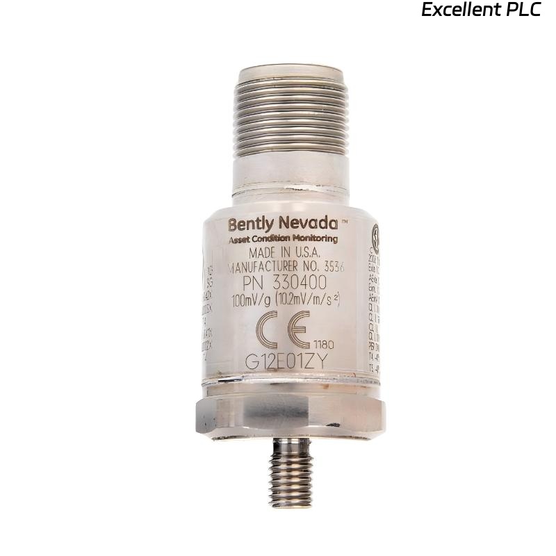
The Bently Nevada 330400-00-00 accelerometer is engineered to deliver clean, high-frequency vibration data for critical rotating equipment. However, when installed near high-power electrical sources, the sensor’s analog output can become polluted by Electromagnetic Interference (EMI) or Radio Frequency Interference (RFI), resulting in distorted waveforms and false alarms.
This article outlines how EMI/RFI affects the sensor, how to diagnose the problem, and field-proven engineering solutions.
1. A Real Industrial Scenario
Application: Steam turbine gearbox
Monitoring System: 3500/42M Proximitor/Accelerometer Module
Sensor Cable Length: ~20 meters
Nearby Device: Variable Frequency Drive (VFD) for extraction pump
Operators noticed abnormal wideband noise in vibration data after the VFD retrofit.
2. Symptom Description
The following data anomalies were observed:
-
FFT spectrum showing broadband spikes between 10 kHz – 100 kHz
-
Non-mechanical periodic noise synchronized with VFD switching frequency
-
HMI vibration trends showing unstable amplitude jumps
-
Diagnostic software reporting “Input Noise Floor Elevated”
-
No mechanical damage confirmed through borescope and bearing inspection
Notably, the noise disappeared when the VFD was temporarily de-energized, confirming EMI involvement.
3. How EMI/RFI Affects the 330400-00-00 Sensor
Signal Transmission Vulnerabilities
The accelerometer outputs low-voltage analog signals, which are sensitive to:
-
Inductive coupling (from high-current power cables)
-
Capacitive coupling (from switching power electronics)
-
Radiated RF fields (from wireless transmitters or inverters)
Common EMI/RFI Sources in Plants
| EMI Source | Interference Mode |
|---|---|
| VFD / Inverters | High-frequency switching noise |
| Soft starters | Harmonic distortion |
| Welding machines | Transient spikes |
| Two-way radios | Radiated RF bursts |
| Radar systems | RF pulsed interference |
| Transformers / contactors | Inductive spikes |
The 330400-00-00 sensor cable acted as an antenna, picking up radiated EMI and injecting it into the monitoring system.
4. Diagnostic Methods Used
Field engineers used multiple techniques:
(1) Comparative Sensor Testing
Swapped the accelerometer input channel with a prox probe channel → noise remained on accelerometer side, confirming sensor path sensitivity.
(2) Cable Routing Inspection
Found cable routed parallel to VFD output cables for several meters, increasing inductive coupling.
(3) Oscilloscope Measurements
Measured sensor output directly and found:
-
Burst-type high-frequency noise during VFD load changes
-
No waveform distortion when VFD disabled
(4) Grounding and Shield Inspection
Detected shield grounding only on one side, leading to poor EMI rejection.
5. Corrective Measures Implemented
A. Cable Shielding & Routing Optimization
✔ Rerouted accelerometer cable away from high-current paths
✔ Separated signal cables at least 30 cm from VFD cables
✔ Ensured twisted-pair wiring for noise rejection
B. Shielding & Grounding Enhancements
✔ Shield terminated at single-point ground
✔ Ground loops eliminated
✔ Conductive bonding improved between cabinet and field junction box
C. Signal Conditioning Fixes
✔ Installed inline ferrite cores near acquisition module
✔ Added EMI filters on cabinet power feeds
✔ Verified module impedance match for accelerometer input
After these improvements, signal distortion disappeared and vibration readings matched mechanical reality.
6. Preventive Recommendations for EMI-sensitive Installations
| Recommendation | Benefit |
|---|---|
| Avoid parallel routing with VFD motor leads | Reduces inductive coupling |
| Use low-impedance cable shielding | Improves signal integrity |
| Verify single-point grounding | Prevents ground loops |
| Install line filters and ferrites | Suppresses high-frequency noise |
| Conduct EMI audits after retrofits | Catches problems early |
These steps are particularly critical when upgrading to VFD-driven systems in refineries, power plants, and chemical facilities.
7. Key Engineering Takeaways
-
EMI noise can mimic actual vibration, misleading maintenance teams
-
330400-00-00 sensors are robust, but signal chain integrity must be protected
-
Cable routing and grounding practices are as important as sensor selection
-
EMI issues often surface after electrical retrofits or equipment modernization
Conclusion
Electromagnetic interference can significantly degrade the signal quality of a Bently Nevada 330400-00-00 accelerometer, leading to poor fault diagnostics and unnecessary shutdowns. Proper cable shielding, grounding, routing, and EMI filtering ensures reliable plant vibration monitoring and machinery protection.