

Table of Contents
- Bently Nevada 330400-02-BR Accelerometer Role in Vibration Monitoring
- Bently Nevada 330400-02-BR Sensor Mounting Strategy and Risks
- Bently Nevada 330400-02-BR Accelerometer Wiring and Signal Interface Setup
- Bently Nevada 330400-02-BR System Configuration and Signal Scaling
- Bently Nevada 330400-02-BR Commissioning and Signal Validation
Bently Nevada 330400-02-BR Accelerometer Role in Vibration Monitoring
Bently Nevada 330400-02-BR accelerometer installation errors typically lead to distorted vibration readings rather than sensor failure. In most cases, incorrect mounting or poor signal routing causes abnormal data during Setup and Commissioning.
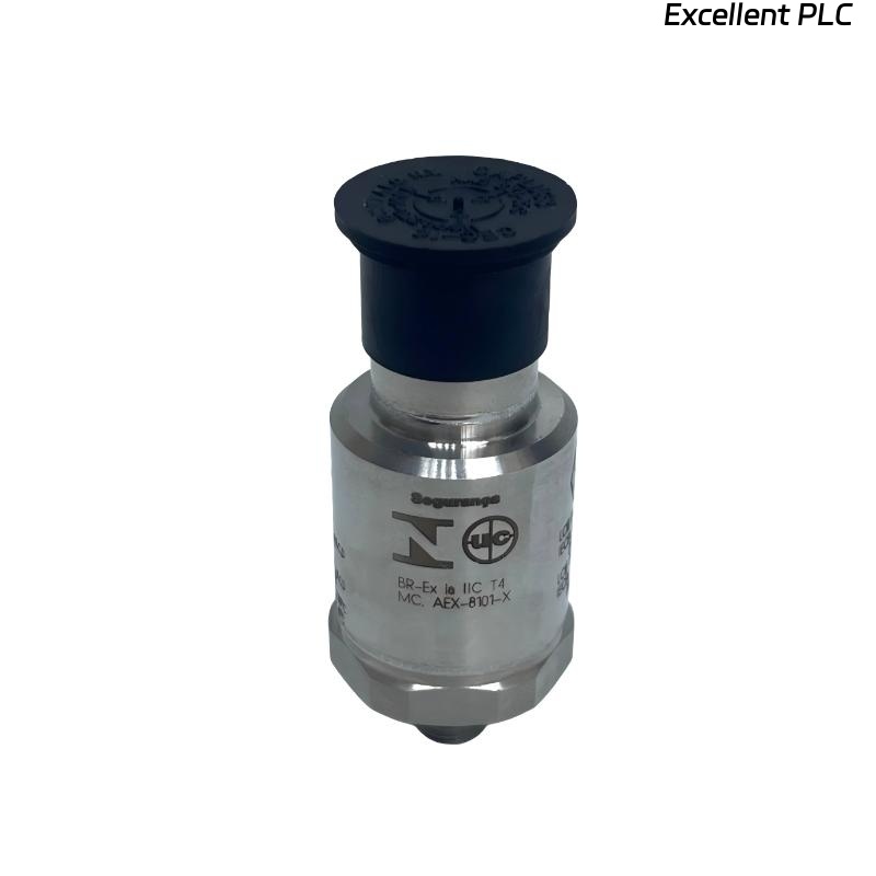
This accelerometer is widely used in rotating equipment such as pumps, compressors, and turbines where accurate vibration monitoring is essential for predictive maintenance.
Bently Nevada 330400-02-BR Sensor Mounting Strategy and Risks
The most critical step in the Installation Guide is sensor mounting. Signal quality depends heavily on mechanical coupling.
- Preferred method: stud mounting (M5 or 1/4-28 UNF)
- Avoid magnetic bases for permanent installations
- Mount on rigid surface close to bearing housing
- Surface roughness < 1.6 μm recommended
In one field case, a sensor installed with adhesive showed vibration values of 18 mm/s. After switching to stud mounting, readings dropped to 6 mm/s, aligning with actual machine condition.
Bently Nevada 330400-02-BR Accelerometer Wiring and Signal Interface Setup
Proper wiring ensures stable signal transmission to PLC Controller or monitoring systems.
- Use shielded twisted pair cables
- Connect shield at one end only (typically control cabinet)
- Maintain separation from high-voltage cables (> 30 cm)
# Signal check procedure
MEASURE SENSOR OUTPUT (mV)
VERIFY SHIELD CONTINUITY
CHECK GROUND LOOP PRESENCE
We observed that routing sensor cables parallel to motor power cables introduced noise spikes up to ±2 mV, affecting vibration analysis.
Bently Nevada 330400-02-BR System Configuration and Signal Scaling
During Setup, correct System Configuration is required to interpret sensor output:
- Set input type (accelerometer signal)
- Configure scaling (e.g., 100 mV/g)
- Define filtering (low-pass or band-pass)
- Assign channel in monitoring system or PLC Module
In one commissioning project, incorrect scaling caused readings 10x higher than actual values. After recalibration, vibration dropped from 50 mm/s (false) to 5 mm/s (actual).
Bently Nevada 330400-02-BR Commissioning and Signal Validation
Commissioning should validate both mechanical and electrical integrity:
- Compare readings with reference instrument
- Check noise floor (< 1 mV typical)
- Verify frequency response
- Monitor stability over 30–60 minutes
A real-world validation showed signal drift due to temperature variation. After improving cable insulation, drift reduced by 70%.
A robust Installation Guide combined with careful Setup and Commissioning ensures reliable vibration data and reduces future Troubleshooting effort.