

Recently, I had to install a Bently Nevada 330909-00-80-70-02-05 3300 NSv eddy current probe on a gas turbine rotor. Correct wiring is crucial because even minor mistakes can cause false trips, noise, or signal loss. Here’s a detailed field-proven guide.
Step 1: Pre-Wiring Preparation
Before handling the probe:
-
Ensure the machine and associated monitoring system are powered down.
-
Verify the probe model: 330909-00-80-70-02-05.
-
Inspect the probe cable for any cuts, kinks, or damaged shielding.
-
Prepare tools: small wire strippers, multimeter, torque screwdriver, and heat-shrink tubing if needed.
Step 2: Understanding the Wiring Configuration
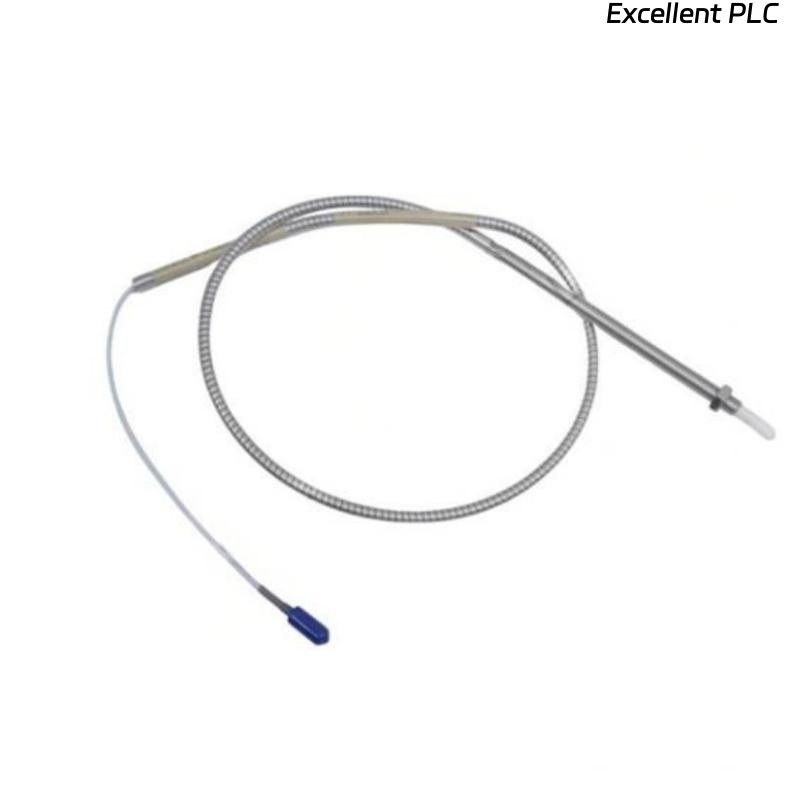
The 3300 NSv eddy current probe uses a coaxial cable with the following configuration:
| Conductor | Function | Connection Notes |
|---|---|---|
| Inner Conductor | Signal | Connects to the “+” or IN terminal on the PROXPAC or 3500 module |
| Shield / Outer Braid | Ground | Connects to the module’s signal ground; must remain continuous |
| Optional Drain Wire | Protective earth | Connect to chassis PE if present |
Key points from field experience:
-
Never let the inner conductor touch the shield — this shorts the signal.
-
Maintain shield continuity from probe tip all the way to the module.
-
Use proper ferrules or soldered connections, depending on the module’s terminal type.
Step 3: Cable Preparation
-
Carefully strip 8–10 mm of the outer insulation without nicking the shield.
-
Twist shield braid neatly; do not fold back too much, leaving enough length to connect to the module terminal.
-
Strip 2–3 mm of insulation from the inner conductor.
-
Optional: use heat-shrink tubing on the junction for mechanical protection.
Step 4: Connection to the Module
When connecting to a Bently Nevada PROXPAC or 3500 series module:
-
Signal (inner conductor) goes to the IN / + terminal.
-
Shield goes to the SG / shield terminal.
-
Ensure the shield does not touch the positive terminal.
-
Tighten terminals to the recommended torque (usually 0.4–0.5 Nm).
Field tip: Loose shield connections are the most common cause of high noise or fluctuating readings. Always test continuity before powering the system.
Step 5: Verification
After wiring:
-
Use a multimeter to confirm no short between signal and shield.
-
If possible, perform a loop test with a Bently Nevada PROX tester.
-
Check the module LED indicators — the corresponding channel should show normal status.
-
Rotate the rotor manually (if feasible) and verify signal variation corresponds to shaft movement.
Step 6: Routing and Mechanical Considerations
-
Avoid sharp bends in the coaxial cable; minimum bend radius should be 10× cable diameter.
-
Keep the cable away from high-voltage or high-current conductors to prevent electromagnetic interference.
-
If routing through tight spaces, consider additional protective conduit.
Step 7: Common Field Mistakes
-
Connecting inner conductor to shield → causes constant zero readings or intermittent faults.
-
Broken shield continuity → introduces signal noise.
-
Excessive stripping or nicked cable → permanent damage to the probe.
-
Loose terminal screws → unreliable readings under vibration.
Step 8: Best Practices
-
Document each probe’s location, channel number, and cable routing.
-
Perform a baseline signal check after installation and note it for future diagnostics.
-
Use proper strain relief near connectors to reduce stress on the cable.
“Even the most sophisticated turbine monitoring system depends on a single tiny conductor being wired correctly.”
Key Takeaways
-
Wiring of the 3300 NSv probe is simple but sensitive — shield integrity and signal isolation are critical.
-
Careful preparation, clean connections, and proper routing prevent most installation failures.
-
Field testing and baseline measurement immediately after wiring saves troubleshooting time later.