

Fault Overview
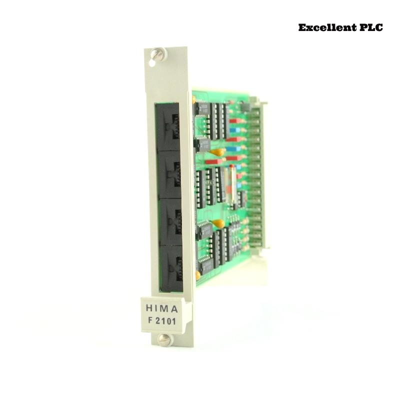
In a Planar F control cabinet, three channels of the Black Horse F2101 4x Relay Amplifier suddenly stopped energizing.
Observed symptoms:
-
PLC outputs active
-
No LED illumination on affected channels
-
No relay click
-
Fourth channel still working
-
Field power stable
The simultaneous failure of multiple channels strongly suggested a shared circuit problem.
Understanding Internal Coil Supply Design
In the F2101 module:
-
Relay coils share a common supply rail
-
Each channel has individual driver transistor
-
Common return path connected internally
-
LED indicators powered from coil supply
If common coil voltage disappears, multiple channels stop working.
Step 1 – Verify Individual Driver Function
1. Compare control signal to working channel.
2. Check base/gate drive voltage.
3. Confirm PLC output stable.
Driver control signals were present on all failed channels.
Step 2 – Measure Coil Supply Voltage
1. Activate failed channel.
2. Measure voltage at coil supply rail.
3. Compare with working channel.
Measured:
-
0V at failed channels’ coil supply
-
24V at working channel coil rail
This indicated segmented supply failure.
Step 3 – Inspect Terminal Block and Internal Bus
1. Power down module.
2. Inspect terminal screws.
3. Measure continuity of coil supply path.
Found:
-
Loose terminal screw at coil supply input
-
Slight carbon discoloration
-
High resistance at input connector
This caused voltage drop across internal bus.
Root Cause – High-Resistance Connection at Coil Supply Input
Because three channels shared the same internal bus branch:
-
Poor contact increased resistance
-
Under load, voltage collapsed
-
Coils failed to energize
The fourth channel was connected to separate internal branch.
Why No Diagnostic Alarm Appeared
The module:
-
Does not monitor coil supply voltage directly
-
Only indicates channel activation
-
Lacks supply fault detection
Therefore, failure appeared as silent output loss.
Step 4 – Voltage Drop Verification
1. Energize working channel.
2. Measure voltage before and after terminal.
3. Calculate voltage drop.
Measured 6V drop across loose connection under load.
Corrective Action Plan
– Clean terminal contact surface.
– Tighten supply terminal to specified torque.
– Replace damaged connector if necessary.
– Perform full load voltage drop test.
After correcting terminal issue, all channels energized normally.
Engineering Best Practices
-
Periodically torque-check terminal screws.
-
Avoid using undersized conductors.
-
Inspect for heat discoloration.
-
Document coil supply wiring clearly.
Grouped failures often originate from shared supply connections.
Conclusion
When multiple channels on the Black Horse F2101 4x Relay Amplifier fail simultaneously, the most common cause is interruption of the common coil supply rail. Structured voltage tracing and terminal inspection quickly isolate the issue and restore stable operation in Planar F systems.