

Fault Overview
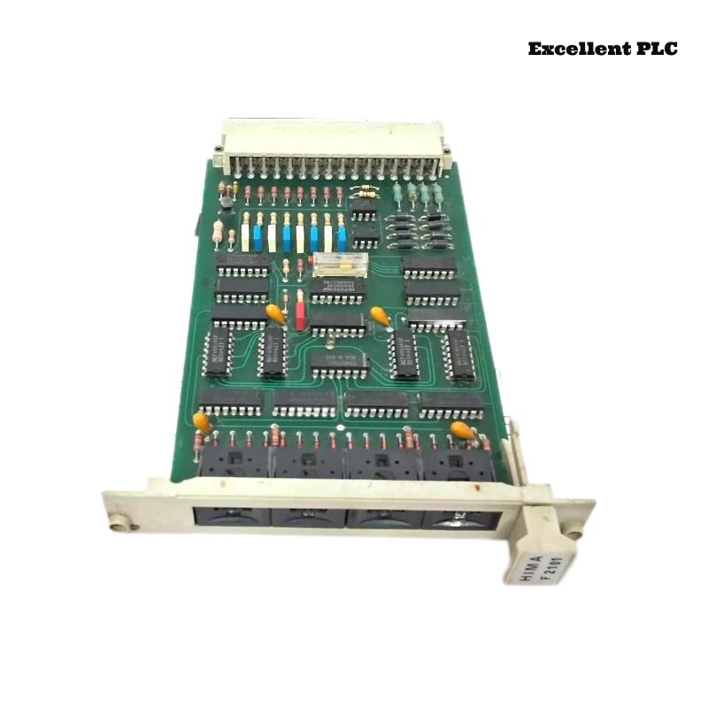
In a Planar F safety panel, one channel of the Black Horse F2101 4x Relay Amplifier remained permanently closed.
Observed symptoms:
-
Field actuator energized continuously
-
Control signal from PLC turned OFF
-
Output LED OFF but load still powered
-
Other channels normal
This pattern immediately suggested mechanical contact welding rather than logic malfunction.
Understanding F2101 Relay Architecture
The F2101 includes:
-
Four independent mechanical relay outputs
-
Galvanic isolation between control and load
-
Coil drive transistor stage
-
Status LED per channel
Unlike transistor modules, mechanical relays are susceptible to contact fusion under high current.
Step 1 – Confirm Control Signal
1. Monitor PLC output command.
2. Verify no force active.
3. Confirm coil drive voltage removed.
Control voltage correctly removed from relay coil.
However, load remained energized.
Step 2 – Verify Relay Mechanical State
1. Power down module.
2. Measure continuity across relay contacts.
3. Compare with healthy channel.
Faulty channel showed permanent continuity across normally open contacts.
This confirmed contact welding.
Root Cause – High Inrush Current
Investigation of connected load revealed:
-
Large capacitive power supply
-
No inrush limiting resistor
-
No surge suppression
-
Frequent switching cycles
Capacitive loads draw high instantaneous current at energization, often exceeding relay rating.
Repeated arcing caused micro-welding until contacts fused permanently.
Why LED Showed OFF
The LED only indicates coil energization status.
Even when coil is de-energized:
-
Welded contacts remain physically closed
-
Electrical continuity persists
Thus LED state does not guarantee contact state.
Step 3 – Load Current Analysis
1. Connect current probe.
2. Monitor first 100 ms of switching.
3. Record peak inrush value.
Measured peak exceeded relay rating by 3–4 times.
Corrective Action Plan
– Replace F2101 module.
– Install inrush current limiter (NTC or resistor).
– Add RC snubber for inductive loads.
– Verify load rating compatibility.
After installing inrush limiter, replacement module operated reliably.
Engineering Best Practices
-
Always evaluate inrush current, not only steady-state current.
-
Avoid switching large capacitive loads directly.
-
Use interposing contactors for heavy loads.
-
Keep switching frequency within relay endurance limits.
Mechanical relay longevity depends heavily on load characteristics.
Conclusion
A permanently closed relay channel on the Black Horse F2101 4x Relay Amplifier is typically caused by contact welding due to excessive inrush current. Proper load analysis and surge suppression prevent recurrence and ensure reliable operation in Planar F systems.