

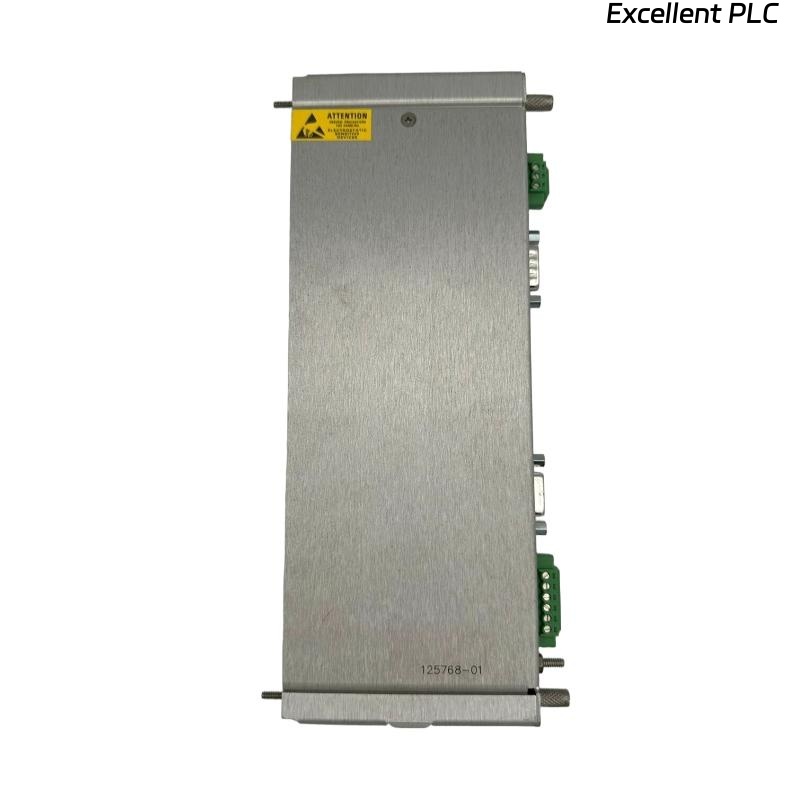
Recently, I installed a Bently Nevada 3500/20 125768-01 RIM I/O module in a turbine monitoring system. This module interfaces with multiple channels for analog and digital signals and is crucial for reliable machine condition monitoring. Here’s my step-by-step, field-proven guide.
Step 1: Pre-Installation Safety and Preparation
-
Power down the 3500 rack and ensure all AC/DC power is isolated.
-
Confirm the module part number: 3500/20 125768-01.
-
Inspect the module for physical damage, bent pins, or contamination.
-
Gather tools: torque screwdriver, multimeter, ESD wrist strap, and wire labeling markers.
-
Prepare the wiring diagrams and channel assignments from the OEM documentation.
Safety tip: Even momentary static discharge can damage sensitive I/O circuits.
Step 2: Rack Slot Identification
-
Identify the correct RIM slot in the 3500 rack.
-
Slide the module into the DIN rail guides carefully.
-
Ensure the module locks firmly in place; you should hear or feel a click.
-
Confirm that front LEDs are off before powering the rack.
Field insight: Installing in the wrong slot can cause channel misassignment and inaccurate monitoring.
Step 3: I/O Wiring Preparation
The RIM I/O module handles both analog and digital signals. Proper wiring ensures accurate monitoring:
Terminal Overview
| Terminal | Function | Notes |
|---|---|---|
| AI+ / AI– | Analog input positive/return | Connect from sensors (vibration, temperature) |
| DI+ / DI– | Digital input | Connect from contact switches or relay signals |
| DO+ / DO– | Digital output | Connect to alarms, trip relays, or external devices |
| SG | Signal ground | Connect shield/ground from sensors |
| PE | Protective earth | Optional, to chassis ground |
Wiring Steps
-
Strip cables carefully: 8–10 mm for outer insulation, 2–3 mm for inner conductors.
-
Twist shield braid neatly for analog inputs.
-
Connect analog inputs to AI+ / AI– terminals.
-
Connect digital signals according to channel assignment.
-
Connect signal ground (SG) from all sensor shields to the SG terminal.
-
Optional: connect PE for protective grounding.
-
Tighten all terminals to recommended torque (~0.4–0.5 Nm).
Field tip: Improper grounding or loose shields are the most common cause of signal noise.
Step 4: Power-Up and LED Verification
-
Apply power to the 3500 rack.
-
Observe LED indicators:
-
Green PWR – Module powered correctly
-
Yellow WARN – Input signal abnormality
-
Red FAULT – Module fault or wiring issue
-
Troubleshooting tip: If FAULT LED is on, check wiring polarity, shield continuity, and verify module seating.
Step 5: System Configuration
-
Use 3500 system software to assign channels.
-
Configure each analog input: type, range, alarm thresholds.
-
Configure digital inputs/outputs as necessary for interlocks and trips.
-
Verify communication between module and central monitoring station.
Step 6: Field Verification and Testing
-
Use a multimeter or test signal generator to verify analog input readings.
-
Test digital inputs by triggering the connected switches or relay outputs.
-
Activate alarms or trips in software to ensure DO channels respond correctly.
-
Record initial baseline readings for each channel.
Field tip: Always verify each channel individually before full system startup.
Step 7: Example Structured Test Code
Here’s a simple Structured Text snippet for monitoring analog and digital inputs:
-
Use this logic to verify that both AI and DI signals are received correctly and DO channels respond as expected.
Step 8: Common Field Issues
-
Incorrect channel wiring → wrong readings or false alarms.
-
Loose shielding or ground connections → noise on analog channels.
-
Reversed polarity on digital signals → DO outputs may fail.
-
Module not seated properly → intermittent faults.
Step 9: Best Practices
-
Label all cables for each channel.
-
Keep wiring organized and away from high-current lines to reduce EMI.
-
Document module serial number, channel mapping, and sensor connections.
-
Capture baseline measurements immediately after installation for future comparison.
-
Consider installing strain relief on input/output cables.
Field Takeaways
-
The 3500/20 RIM I/O module is critical for both analog and digital monitoring.
-
Accurate wiring, grounding, and configuration are essential for reliable operation.
-
Baseline verification and software testing prevent field failures and ensure long-term monitoring integrity.
“The reliability of your 3500 system depends on meticulous installation — every wire, every shield, every channel matters.”