

Typical Fault Symptoms
Below are common fault indicators and behaviours you may encounter:
-
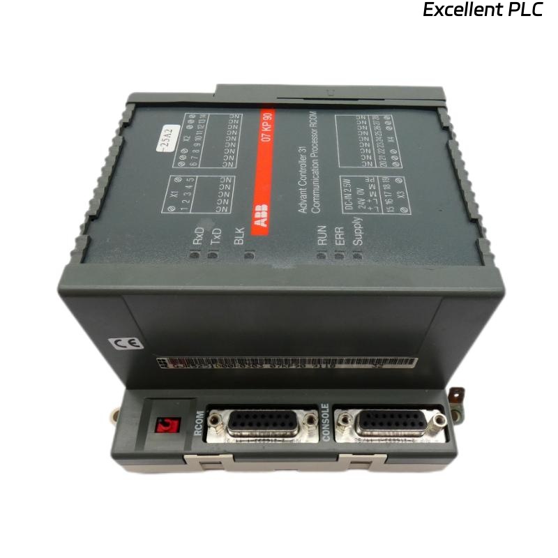
The module’s Supply LED is off: no 24 V DC supply detected.
-
The RUN LED is off or stays off: module not ready for communication.
-
The ERR LED is red or remains lit continuously: fatal RCOM communication error or hardware fault.
-
The BLK LED is yellow: indicates “Transmission of user data blocked as the result of communication error”.
-
Data link down: slave modules not responding, master indicates timeout or checksum error if monitoring via SCADA or PLC.
Preliminary Safety & Preparation
Before you begin physical repair or troubleshooting, ensure you follow these best practices:
-
Power down the system: Switch off the 24 V DC supply and ensure that the basic unit is de‑energised before removing or installing the 07 KP 90 module.
-
Observe ESD precautions: The module contains internal memory (RAM, EPROM, DP‑RAM) and may suffer damage from static discharge.
-
Document current configuration: Note communication settings (baud rate, RS‑232 vs RS‑485, master/slave roles) so you can restore them after repair.
-
Ensure proper earthing/grounding: Correct earthing of the switch‑gear cabinet and shielded cables for serial/RCOM interfaces is critical.
Step‑by-Step Troubleshooting & Repair Procedure
Step 1: Check Supply Voltage and Physical Mounting
-
Confirm the 24 V DC supply is present at the terminal block.
-
Verify the module is properly mounted on the DIN rail; vibration or loose mountings may lead to intermittent faults.
-
Examine the earth terminal and ensure continuity of earthing cable.
If supply is absent or incorrect:
-
Check upstream fuses, wiring from the basic unit, and proper voltage.
-
Repair or replace wiring or supply module as needed. Then power on and monitor LEDs.
Step 2: Observe LED Diagnostics
-
Power on module and observe LED status:
-
Supply LED should be green.
-
RUN LED should be green.
-
RxD/TxD LEDs will flash when communication telegrams are received/transmitted.
-
BLK LED indicates blocked user-data transmission.
-
ERR LED red and stays on indicates fatal error or hardware fault.
-
Interpretation:
-
Only Supply LED off → supply failure.
-
Supply on, RUN off → module did not initialise, possible internal fault or incompatible basic unit.
-
RUN green but BLK on → communications path blocked, likely configuration or cabling issue.
-
ERR red and constant → hardware fault; module may need replacement.
Step 3: Verify Communication Cabling and Interfaces
-
Check RCOM serial interface wiring (RS‑232 or RS‑485).
-
Ensure shielded twisted‑pair cabling for RS‑485, terminated properly at ends; verify no ground loops.
-
Inspect the networking interface between 07 KP 90 and basic unit.
-
Confirm baud rate, parity, stop bits and mode in PLC/SCADA system match module settings.
If cabling or interface issue suspected:
-
Replace cable or swap with known good unit to isolate.
-
Re‑terminate shield grounding correctly.
Step 4: Reset / Re‑Initialise Module
-
For recoverable communication errors, switch supply voltage off then on again for both the 07 KP 90 and the basic unit.
-
After restart, check if ERR LED clears and RUN LED goes green.
Step 5: Replace Module or Firmware (if applicable)
-
Persistent ERR LED or RUN never going green → hardware fault (RAM/EPROM/DP‑RAM). Replacement required.
-
Check firmware compatibility with the basic unit.
-
When installing a replacement, ensure the same revision level or revalidate system configuration.
Step 6: Validation & Monitoring
-
Once operational (RUN green, no ERR, RxD/TxD flashing, BLK off), monitor communication over time.
-
In PLC/SCADA system, monitor typical error codes (Timeout, Checksum error, Address error).
-
Document any changes, date of repair, module revision, and monitor for repeat faults.
Best Practices to Prevent Recurrence
-
Ensure good earthing and shielding of communication cables.
-
Keep module firmware and system documentation updated.
-
Maintain an inventory of known‑good spare modules.
-
Monitor ambient temperature and mounting; ensure proper natural convection cooling.
-
Regularly inspect cables for wear, movement, or vibration.
Conclusion
Faults in the ABB 07 KP 90 communication module can often be resolved by systematic diagnosis of supply voltage, LED indicators, cabling, and configuration, along with reset procedures. When a hardware fault is identified (persistent ERR LED), module replacement is the reliable solution. Following these steps and best practices restores reliable communications and helps prevent future failures.