

Introduction
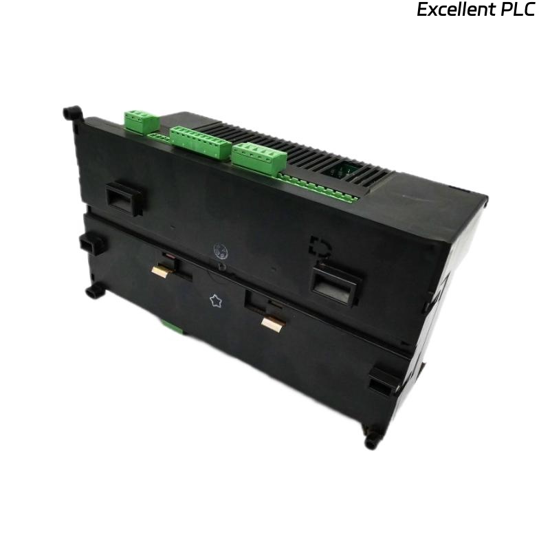
The ABB 07KT92C (part number GJR5250500R0202) is a central processing unit (CPU) in the AC31 / Advant Controller series, used in industrial automation systems. It supports a 24 V DC supply, digital and analog I/Os, and serial communication interfaces.
When the 07KT92C fails, you may encounter system halts, I/O non‑response, unexpected resets, or diagnostic LED faults. This tutorial provides a fact‑based, step‑by-step maintenance and repair guide tailored for technician use and optimized for search‑engine visibility.
Component Overview & Typical Specifications
-
Model: 07KT92C (GJR5250500R0202)
-
Supply: 24 V DC nominal
-
I/O Capability: up to 1000 digital I/Os, up to 224 analog I/Os
-
Serial Interfaces: two RS‑232 ports plus RS‑485 bus support
-
Platform: part of ABB’s AC31 / Advant Controller 31 intelligent automation system series
Understanding these specs helps with diagnosing faults such as supply issues, I/O overload, and bus communication errors.
Typical Fault Symptoms
-
CPU fails to power up or RUN LED does not turn on.
-
Unexpected resets, stuck tasks, or high cycle times.
-
Remote I/O modules become non‑responsive or show bus errors.
-
Diagnostic flags in the PLC program indicate memory faults, task time overrun, or configuration errors.
-
EMC/grounding‑related disturbances: noise, interference, modules resetting or halting.
Safety & Preparation
-
Power off the 24 V DC supply before removing or inserting the CPU.
-
Observe ESD precautions: the CPU has internal memory (non‑volatile, flash or EPROM).
-
Document current configuration: firmware version, program version, bus settings, I/O counts, network addresses.
-
Confirm proper grounding/earthing of the cabinet, CPU, and bus‑interface shields.
-
Ensure ambient conditions meet the original AC31 specifications.
Step‑by-Step Troubleshooting & Repair Procedure
Step 1: Check Supply Voltage and Physical Condition
-
Confirm 24 V DC supply is present at the terminal block.
-
Ensure power connectors and bus connectors are firmly seated.
-
Check CPU mounting on DIN rail or baseplate.
-
Inspect grounding/earthing connection.
If supply is absent or unstable:
-
Check upstream fuse(s), supply module, and wiring integrity.
-
Repair or replace wiring/supply before proceeding.
Step 2: Observe LED Indicators & Diagnostic Flags
-
Power/Run LED: Should indicate CPU operational (green).
-
Error/STAT LED: Indicates internal fault, memory, or bus error.
-
Check diagnostic words in the user program for error codes.
Interpretation:
-
No RUN LED → CPU may not initialise.
-
RUN OK but frequent resets → memory corruption, overheating, or bus/grounding issues.
-
Bus or I/O modules not responding → investigate communication interface and peripheral modules.
Step 3: Verify Communication and I/O Interfaces
-
Confirm bus wiring intact, terminated correctly, no ground‑loops.
-
Check serial ports: RS‑232/RS‑485 configuration matches connected devices.
-
Inspect connected I/O modules for loose connectors or failures.
-
Ensure bus addresses are unique and match configuration.
If communication fault found:
-
Replace suspect cabling or modules.
-
Check termination resistors and shielding.
Step 4: Memory, Firmware and Configuration Checks
-
Ensure CPU firmware matches user program version and hardware revision.
-
Check for memory corruption if CPU fails to start or shows memory fault.
-
Backup user program before any re-initialization.
-
Verify configuration constants after changes in I/O or bus topology.
Step 5: Reset, Replace or Service CPU
-
Attempt cold start (power down, wait, power up) for non‑critical faults.
-
Persistent memory faults or failure to run → CPU replacement or professional service required.
-
Ensure replacement CPU is same model and revision; reload configuration and test functionality.
Step 6: Validation & Monitoring
-
Confirm CPU runs stable: RUN LED on, no resets, tasks within cycle time.
-
Monitor diagnostic areas for CPU utilization and task overrun flags.
-
Monitor I/O modules and bus data exchange for errors.
-
Document repair activity: date, module revision, fault code, root cause, corrective action.
Best Practices to Prevent Recurrence
-
Maintain proper grounding and shielding of cabinet and communication cables.
-
Keep firmware and documentation archived.
-
Maintain a spare CPU module for critical systems.
-
Monitor ambient conditions: ensure cooling and ventilation.
-
Inspect wiring periodically for wear, vibration, or loose connectors.
-
Plan migration strategy as AC31 series is discontinued.
Conclusion
The ABB 07KT92C (GJR5250500R0202) CPU is a legacy but widely used automation component. Faults are typically related to supply, LEDs/diagnostics, communication interfaces, memory/firmware, and configuration. Following this systematic guide and preventive maintenance practices restores reliable operation and reduces downtime.