

During a recent maintenance project, I encountered an issue while wiring a Schneider 170ADO35000 discrete output module on a Modicon Quantum PLC system. The problem was simple but common — multiple output connectors were available, and it wasn’t immediately clear which terminal corresponded to which output channel. Improper insertion could easily result in blown fuses or short circuits. Here’s how I verified and correctly wired the module, step by step, based on hands-on experience.
Step 1: Understanding the Module’s Structure
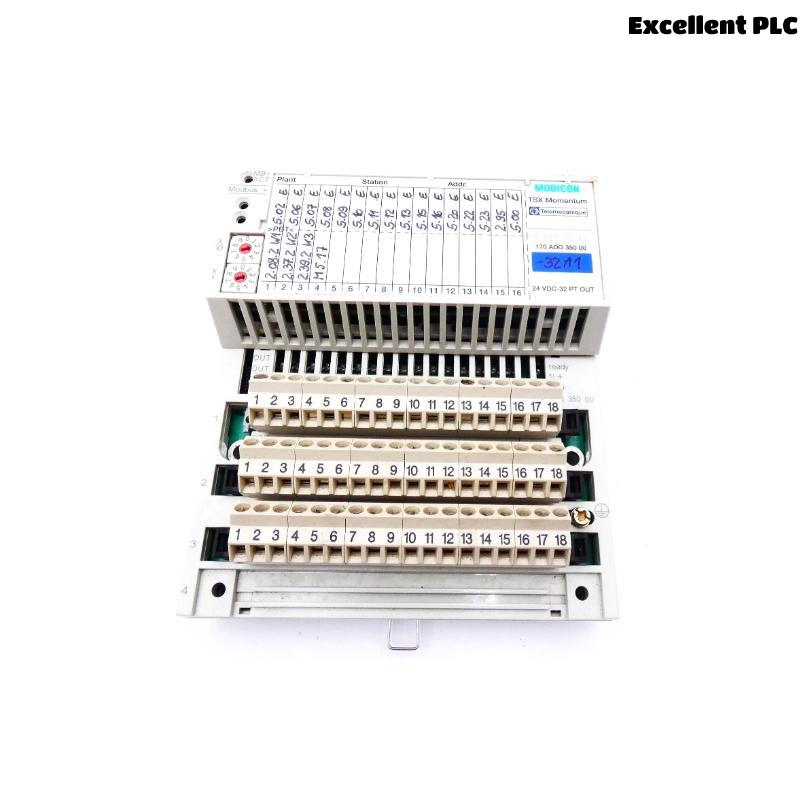
The 170ADO35000 is a 32-point discrete output module that operates typically at 24 VDC. It has two 18-pin removable terminal connectors (marked as Top and Bottom), each responsible for 16 outputs.
-
Top connector: Channels 0–15 (O0–O15)
-
Bottom connector: Channels 16–31 (O16–O31)
Each connector includes its own common (COM) line, typically grouped by 8 channels. This means:
-
O0–O7 share COM1
-
O8–O15 share COM2
-
O16–O23 share COM3
-
O24–O31 share COM4
Understanding this grouping is essential because plugging the connectors incorrectly can cross-bridge commons and cause signal errors or hardware damage.
Step 2: Identifying the Correct Connector Orientation
Before inserting any connectors, I checked the keying notch on the terminal block — it prevents incorrect insertion, but in older or worn connectors, it’s still possible to misalign pins slightly.
Here’s what I did:
-
Removed both connectors carefully.
-
Checked for the small plastic key slot on the left side — that aligns with the notch on the module.
-
Ensured all wires were routed downward and labeled according to the channel mapping from the wiring diagram.
-
Used a continuity tester to confirm each wire from the field terminal matched the expected output channel.
Step 3: Verifying Output Channel Mapping
I cross-checked the channel mapping from the Schneider wiring diagram (from the Quantum hardware manual). For the 170ADO35000:
| Output | Connector | Pin | Description |
|---|---|---|---|
| O0–O7 | Top | 1–8 | First output group |
| COM1 | Top | 9 | Common return for O0–O7 |
| O8–O15 | Top | 10–17 | Second output group |
| COM2 | Top | 18 | Common return for O8–O15 |
| O16–O23 | Bottom | 1–8 | Third output group |
| COM3 | Bottom | 9 | Common return for O16–O23 |
| O24–O31 | Bottom | 10–17 | Fourth output group |
| COM4 | Bottom | 18 | Common return for O24–O31 |
This table helped me quickly verify which connector should go where and how to label the field wiring.
Step 4: Inserting the Connectors Properly
Once everything was double-checked, I reconnected both terminal blocks carefully:
-
Inserted the top connector first, applying gentle pressure until it clicked into place.
-
Checked alignment visually to ensure no bent pins.
-
Inserted the bottom connector in the same way.
-
Gave each connector a light pull to confirm a firm connection.
⚙️ Important tip: Never force a connector that doesn’t fit easily — if it resists, stop and recheck the pin alignment. These connectors are delicate, and a single bent pin can cause an entire channel group to fail.
Step 5: Power-Up and Functional Testing
After reconnecting, I powered up the PLC and observed the channel status LEDs on the 170ADO35000 module.
-
Each channel LED corresponds to one output.
-
When I forced outputs via EcoStruxure Control Expert, each LED lit correctly according to the programmed logic.
I also used a multimeter to measure the output voltage at each terminal. All outputs responded properly, and the commons were consistent at 0V.
If an output didn’t respond, I checked both the connector seating and the field wire continuity — in most cases, poor contact or misalignment was the cause.
Step 6: Troubleshooting Common Issues
Here are some practical lessons learned from this and previous installations:
-
Issue: Output LED on but no field signal.
→ Check for broken or loose terminal wires, or verify the external load is functional. -
Issue: Multiple outputs toggling together.
→ Usually caused by shared commons wired incorrectly. Verify each group’s COM line is isolated. -
Issue: Module communication OK but random channel failures.
→ Often a sign of bent connector pins or oxidation on contacts. Clean gently with contact cleaner.
Step 7: Final Verification
After confirming proper operation, I labeled both connectors clearly with:
-
Connector position (Top / Bottom)
-
Channel range (0–15, 16–31)
-
Common reference number
I also added a small note near the panel:
“170ADO35000 Output Module – Connector Mapping Verified – Date: [YYYY-MM-DD]”
This helps future maintenance teams identify the connections quickly without rechecking diagrams.
Key Takeaways
-
Always verify channel-to-connector mapping before wiring.
-
Never assume the top and bottom connectors are interchangeable — they’re not.
-
Proper labeling and documentation save significant time in future maintenance.
-
Test all channels with both software and multimeter verification.
-
Avoid forcing connectors — one bent pin can lead to costly downtime.
Closing Thoughts
The Schneider 170ADO35000 is a reliable discrete output module, but its multiple connectors can cause confusion if wiring is not clearly identified. A methodical, step-by-step approach — from verifying pin mapping to confirming output response — ensures the module performs flawlessly. Taking a few extra minutes to document and label connections during installation can prevent hours of troubleshooting later on.