

1. Overview
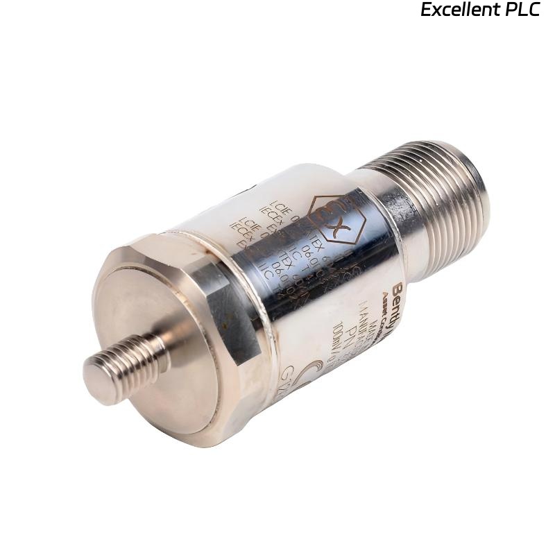
Model: Bently Nevada 330400-00-00 Accelerometer
Monitoring System: Bently 3500 Machinery Protection System
Application: Hot-end turbine bearing housing
Operating Environment: Continuous 24/7 operation at elevated temperatures
This report documents a thermal degradation failure affecting the accelerometer and outlines diagnostic findings, root cause analysis, corrective actions, and long-term preventive strategies.
2. Problem Description
During a routine vibration survey, analysts detected:
-
Gradually decreasing vibration amplitude over several months
-
FFT spectrum losing high-frequency content
-
Poor response above 5 kHz (attenuation effects)
-
Accelerometer output drift under high load
-
Increased sensor noise floor at operating temperature
Initially misinterpreted as mechanical improvement, data trend review revealed the issue aligned with seasonal temperature increases, indicating thermal sensitivity drift rather than a real change in machine condition.
3. Failure Symptoms Observed in the Field
The following anomalies were tied to temperature exposure:
| Symptom | Manifestation |
|---|---|
| Amplitude attenuation | Lower vibration RMS values than expected |
| Frequency loss | FFT unable to resolve high-frequency bearing faults |
| Output drift | Slow baseline shift during thermal cycles |
| Noise increase | Elevated broadband noise at high temperatures |
| Intermittent dropouts | Temporary loss during peak thermal load |
These behaviors can mask bearing defects, impacting predictive maintenance effectiveness.
4. Root Cause Analysis
Investigation identified multiple contributing factors:
A. Sensor Material Limitations
The 330400-00-00 uses a piezoelectric sensing element with thermal limits. Prolonged exposure near or above rated temperatures caused:
-
Piezoelectric coefficient reduction
-
Loss of sensitivity
-
Internal damping increase
B. Cable and Connector Degradation
High-temperature exposure affected:
-
Cable jacket flexibility
-
Shield integrity
-
Connector sealing
These factors contributed to noise and signal attenuation.
C. Mounting Surface Heat Transfer
The sensor was mounted directly on a high-temperature bearing housing without thermal isolation, causing conductive heat transfer into the sensor body.
5. Diagnostic Process
A combination of lab and field diagnostics was applied:
-
Temperature Logging
-
Thermocouple readings confirmed sensor case temperature exceeded recommended limits.
-
-
Sensor Replacement A/B Comparison
-
New sensor restored normal amplitude and HF response, confirming sensor degradation.
-
-
Spectrum Analysis
-
Recovered >10 kHz content after sensor replacement, confirming temperature-induced attenuation not mechanical defect.
-
-
Material and Cable Inspection
-
Cable jacket showed heat hardening and micro-cracking.
-
-
Infrared Thermal Imaging
-
IR camera revealed direct conduction path from bearing surface into sensor body.
-
6. Corrective Actions Implemented
To restore reliable vibration monitoring, the following measures were taken:
✔ Sensor Relocation or Isolation
-
Installed thermal isolation washer
-
Modified mounting location to reduce heat transfer
✔ Cable Upgrade
-
Replaced cable with high-temperature rated variant
✔ Sensor Replacement
-
Installed a new 330400-00-00 sensor and recalibrated channel
✔ Thermal Shielding
-
Added reflective shielding between hot surface and sensor
✔ Control System Adjustment
-
Validated 3500 channel settings after replacement
Following modifications, spectral clarity and amplitude accuracy were restored.
7. Preventive Strategies for High-Temperature Machinery
To prevent similar failures, field engineers are advised to:
A. Temperature Control
-
Keep sensor body temperature within manufacturer limits (typically <120°C depending on spec)
-
Use IR cameras during shutdown inspections
B. Material Selection
-
Use high-temp cable jackets (e.g., Teflon, PFA, FEP)
-
Avoid PVC or low-temp compounds near hot zones
C. Mechanical Installation
-
Apply thermal isolators or washers
-
Maintain proper torque to avoid thermal loosening
D. Monitoring & Trending
-
Trend amplitude vs. temperature for early detection
-
Flag sudden HF attenuation as thermal-related degradation
8. Engineering Lessons Learned
-
Gradual amplitude reduction is often misinterpreted; sensor health must be considered.
-
High-frequency data is essential for detecting early-stage bearing faults; thermal degradation jeopardizes predictive reliability.
-
Cable and connector temperature limits must match sensor capability.
-
Thermal environment should be evaluated during machinery upgrades or insulation changes.
Conclusion
High-temperature environments can degrade the performance of the Bently Nevada 330400-00-00 accelerometer, resulting in reduced sensitivity, signal distortion, and compromised machinery protection. Through proper thermal management, material selection, installation practices, and preventive monitoring, facilities can maintain accurate vibration measurements and avoid undetected machine damage.