

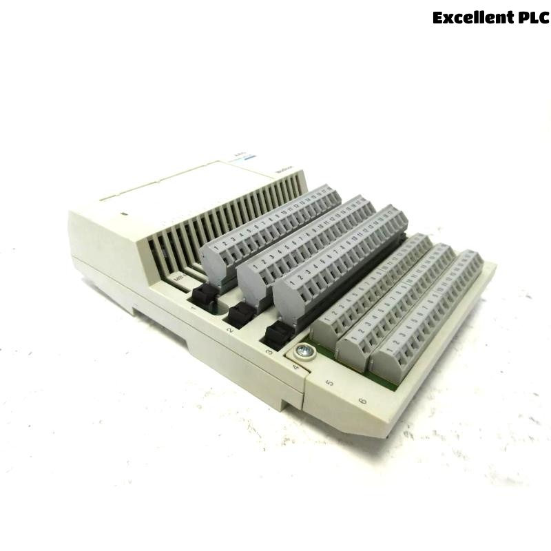
Last month, during a scheduled shutdown, I came across an issue with a Schneider 170BDM34200 Modbus Plus TIO input module that had suddenly stopped reading any signals. The PLC system itself was running, but this specific input module wasn’t responding. After checking the basic communication and configuration, it became clear that the input interface of the module was physically damaged. Here’s how I diagnosed and repaired the issue in the field.
Step 1: Initial Observation and Isolation
The first symptom was that the input channels on the 170BDM34200 module were all reading zeros, regardless of the actual field signals. The module’s status LED was solid red, indicating a hardware fault.
To confirm that the issue was isolated to the module itself (and not wiring or software-related), I performed the following checks:
-
Verified that the backplane power was normal using a multimeter (24V DC stable).
-
Swapped the suspected module with another known-good module in the same slot — the replacement worked fine.
-
Moved the faulty module to another rack slot — the problem persisted.
This confirmed the issue was within the module hardware, not the PLC rack or Modbus Plus network.
Step 2: Disassembly and Visual Inspection
After powering down the system, I carefully removed the 170BDM34200 module from the Quantum base. Opening the module housing revealed clear signs of burn marks near the input terminal section — especially around the resistor network and optocoupler input stage.
Using a magnifier, I noticed one opto-isolator chip (marked PC817) had slight discoloration, likely due to overvoltage from a field wiring surge. This type of failure is common in TIO modules that interface directly with external sensors or 24V control circuits.
Step 3: Component Testing
I disconnected the small daughterboard that handles the input conditioning and used a digital multimeter in diode mode to test each optocoupler. Out of eight channels, two had no measurable forward voltage drop — confirming they were open-circuit.
Next, I checked the input resistor array (R-pack). One leg was shorted to ground, which could easily cause false readings or complete input failure.
Step 4: Repair Process
Because replacement components for these modules are standard, I was able to source equivalent parts from our maintenance stock:
-
Optocoupler: PC817 (Sharp or Everlight equivalent)
-
Resistor Array: 4.7kΩ × 8 inline SIP
The repair process went as follows:
-
Desoldered the two damaged optocouplers using a temperature-controlled soldering station at 320°C.
-
Cleaned the PCB using isopropyl alcohol to remove carbonized residue.
-
Replaced the burned resistor array with a new one of matching value and tolerance.
-
Installed the new optocouplers, ensuring the correct pin orientation (pin 1 indicator aligned with silkscreen mark).
-
Reflowed all solder joints under magnification to check for bridging or cold joints.
After reassembly, I ran a continuity test on each input channel from terminal to logic side to confirm proper isolation and signal path integrity.
Step 5: Reinstallation and Functional Test
Once the module was reassembled, I reinstalled it into the PLC rack and powered up the system. The status LED turned green immediately — a good sign.
Using EcoStruxure Control Expert, I forced test signals through the connected input points. All eight channels responded correctly in real time. I also checked Modbus Plus communication with the network diagnostic tool to ensure there were no CRC errors or timeout messages.
After an hour of continuous monitoring, the module remained stable, with no intermittent faults or overheating.
Step 6: Root Cause and Preventive Measures
Further inspection revealed that one of the field input lines had been subjected to a voltage spike from an inductive load that lacked proper suppression. This likely caused the optocoupler and resistor array to fail.
To prevent this from happening again, I added:
-
RC snubber circuits across the inductive load coils.
-
Transient Voltage Suppressor (TVS) diodes on each input line near the terminal block.
-
Verified that all shields and grounds were correctly terminated at a single point to avoid floating potentials.
Since implementing these changes, the module has been operating continuously without any further failures.
Key Lessons from This Repair
-
Always isolate the module before testing — backplane voltages can damage tools or cause short circuits.
-
Visual inspection can reveal a lot — burned components or discoloration usually point to the real cause.
-
Most input stage failures on TIO modules are due to overvoltage or surge from field devices.
-
Keep replacement parts like PC817 optocouplers and resistor arrays in stock — they’re common failure points.
-
Implement surge suppression and grounding best practices to protect replacement modules.
Final Thoughts
The Schneider 170BDM34200 is a reliable Modbus Plus TIO input module when properly protected from external transients. In most cases, even when an interface fails, careful inspection and replacement of low-level components can bring the module back to full function without needing a full replacement — a big cost saver for industrial maintenance teams.