

1️⃣ Module Overview
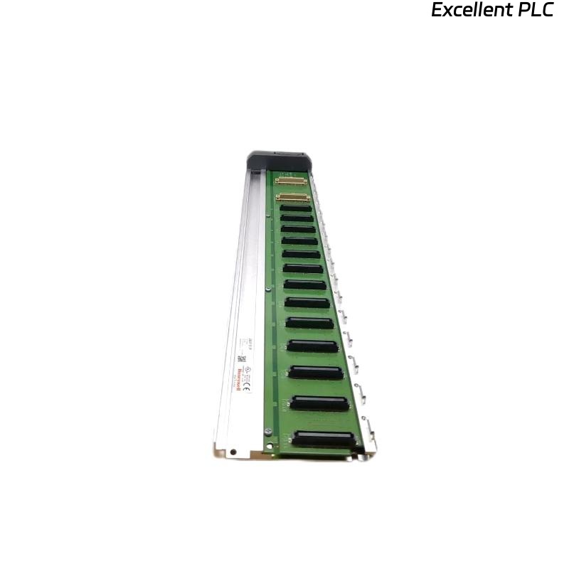
The Honeywell 05427-100 PLC module is part of the HC900 / TDC / Experion PKS automation platform.
It handles control logic, communicates with I/O modules, and manages local and remote process tasks.
Common symptoms of failure:
-
PLC does not execute ladder logic.
-
No response from connected I/O modules.
-
Module LEDs remain off or in error state.
-
Controller fails to initialize during power-up.
2️⃣ Initial Observations
-
LED Status:
-
Power (PWR): Should be solid green.
-
Run (RUN): Blinking green indicates normal logic execution.
-
Fault (FLT/ERR): Red or amber indicates internal error.
-
-
Environmental conditions: Excessive heat, dust, or vibration can trigger module faults.
-
Physical inspection: Look for burnt components, bulging capacitors, or broken connectors.
⚠️ Important: Never power on the module if visible smoke, burn marks, or odor is present.
3️⃣ Step 1 — Power Verification
-
Confirm proper supply voltage: 24 VDC ±10%.
-
Measure at the module input terminals; check for voltage drop under load.
-
Inspect fuse or protective devices in the rack or PLC cabinet.
-
If voltage is missing or unstable, repair or replace the power supply before further testing.
Field note: About 40% of non-working 05427-100 PLC cases are due to power instability or loose terminal connections.
4️⃣ Step 2 — I/O and Communication Check
-
Disconnect peripheral I/O modules and see if the PLC initializes.
-
Check communication cables (RS-485 / serial / Ethernet depending on configuration).
-
Verify connectors for bent pins, corrosion, or loose fit.
-
If using a networked PLC, confirm node address and communication protocol settings.
🔧 Tip: A single miswired I/O or shorted field device can prevent PLC from entering RUN mode.
5️⃣ Step 3 — LED and Self-Diagnostics
-
Observe module LEDs during power-up:
-
Power LED on → module powered
-
Run LED blinking → logic executing
-
Error LED off → normal
-
-
If RUN LED does not blink, or ERR LED is on:
-
Perform self-test using the Honeywell maintenance tool (if available).
-
Check for firmware corruption or missing bootloader sequence.
-
Note any error codes for reference.
-
6️⃣ Step 4 — Firmware and Configuration
-
Ensure module firmware matches system software version.
-
Re-load configuration from backup if corruption is suspected.
-
For standalone tests, connect to a test rack with a known-good CPU or PLC simulator.
Common cause of initialization failure: mismatched firmware or corrupted configuration file.
7️⃣ Step 5 — Hardware Inspection
-
Remove the module carefully and inspect PCB:
-
Burnt resistors, ICs, or diodes
-
Bulging or leaking capacitors
-
Cracked solder joints or traces
-
-
Test internal voltages (5V, 3.3V rails) with a multimeter.
-
If hardware faults are confirmed → module replacement is recommended.
8️⃣ Step 6 — Replacement & Testing
-
Install a known-good 05427-100 module.
-
Power on and observe: PWR solid, RUN blinking, ERR off.
-
Reconnect I/O modules gradually and monitor system logs.
-
Verify ladder logic execution and I/O response.
9️⃣ Preventive Recommendations
| Task | Frequency | Purpose |
|---|---|---|
| Inspect module and rack connectors | 6 months | Prevent oxidation or loose contacts |
| Check cabinet temperature | Monthly | Avoid thermal stress |
| Clean dust from PLC modules | 6–12 months | Maintain airflow and cooling |
| Verify power supply stability | Quarterly | Prevent voltage-related module failures |
| Backup configuration & firmware | After every major update | Rapid recovery after replacement |
🔍 Technical Insight
Based on field data:
-
50–60% of PLC module failures are power or connection-related.
-
20–25% are due to firmware corruption or configuration mismatch.
-
Remaining failures involve internal hardware (capacitors, ICs, or solder joints).
A structured diagnostic approach prevents unnecessary replacements and reduces downtime.
✅ Summary
When a Honeywell 05427-100 PLC module does not operate:
Stepwise approach:
Power → I/O and communication → LED/self-test → Firmware → Hardware → Replacement.
Following these steps ensures reliable troubleshooting and restores PLC operation safely.