 Excellent PLC


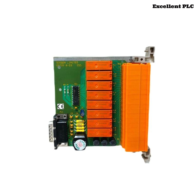
The Honeywell 05701-A-0329 Triple DPCO Relay Card is a high-capacity relay interface module designed for the Honeywell System 57 Gas Detection Controller. Unlike the Triple SPCO Relay Card, the 05701-A-0329 provides Double Pole Changeover (DPCO) relay contacts, offering duplicated outputs for A1, A2, and A3 alarm levels, together with dedicated Fault and Inhibit relay outputs. This configuration enables simultaneous signaling to multiple external systems such as PLCs, DCS controllers, emergency shutdown systems (ESD), audible alarms, and visual warning devices while maintaining complete electrical isolation.
Contents
- 1. Product Overview
- 2. Main Features
- 3. Typical Applications
- 4. Installation Preparation
- 5. Relay Card Installation
- 6. Relay Wiring Connections
- 7. Relay Configuration
- 8. Commissioning Procedure
- 9. Functional Verification
- 10. Preventive Maintenance
- 11. Practical Installation Case
- 12. Frequently Asked Questions
Product Overview
The Honeywell 05701-A-0329 serves as both a field interface card and a Triple DPCO relay module within the System 57 platform. It provides duplicated relay contacts for each alarm level, allowing independent outputs to multiple safety systems without additional interposing relays. The module communicates directly with the Single Channel Control Card and supports configurable relay logic including latching/non-latching and energized/de-energized operation.
Main Features
- Triple Double Pole Changeover (DPCO) relay outputs
- Dual outputs for A1 alarm
- Dual outputs for A2 alarm
- Dual outputs for A3 alarm
- Dedicated Fault relay
- Dedicated Inhibit relay
- Voltage-free relay contacts
- Selectable latching/non-latching operation
- Selectable energized/de-energized logic
- Compatible with Honeywell System 57 controllers
Typical Applications
- Oil and gas production facilities
- Petrochemical plants
- Refineries
- Offshore production platforms
- Chemical processing plants
- LNG terminals
- Power generation stations
- Industrial fire and gas protection systems
Installation Preparation
- Verify the module part number.
- Confirm compatibility with the System 57 rack.
- Disconnect controller power.
- Wear ESD protection equipment.
- Inspect relay connectors and terminals.
- Prepare external alarm wiring.
- Review project wiring drawings.
Relay Card Installation
- Turn off the System 57 controller.
- Locate the relay interface slot.
- Align the 05701-A-0329 with the rack connector.
- Insert the card until fully seated.
- Secure the retaining mechanism.
- Connect all external relay wiring.
- Restore controller power.
Relay Wiring Connections
- Connect both A1 relay outputs.
- Connect both A2 relay outputs.
- Connect both A3 relay outputs.
- Connect Fault relay wiring.
- Connect Inhibit relay wiring.
- Verify protective earth and cable shielding.
- Check terminal tightness.
Relay Configuration
- Select relay operating logic.
- Configure latching or non-latching mode.
- Assign external alarm functions.
- Verify relay contact ratings.
- Check communication with the control card.
- Save configuration parameters.
Commissioning Procedure
VERIFY MODULE INSTALLATION
CHECK FIELD WIRING
VERIFY POWER SUPPLY
CONFIGURE RELAY PARAMETERS
TEST A1 OUTPUTS
TEST A2 OUTPUTS
TEST A3 OUTPUTS
VERIFY FAULT AND INHIBIT RELAYS
CONFIRM NORMAL OPERATION
Functional Verification
- Verify duplicated relay outputs operate correctly.
- Test A1, A2, and A3 alarm relays.
- Verify Fault relay operation.
- Verify Inhibit relay operation.
- Confirm PLC and DCS alarm reception.
- Monitor relay stability during testing.
Preventive Maintenance
- Inspect relay contacts periodically.
- Verify terminal tightness.
- Test relay outputs during scheduled maintenance.
- Inspect field wiring.
- Clean module connectors.
- Review alarm event history.
Practical Installation Case
An offshore gas compression platform required duplicate alarm outputs to both the Emergency Shutdown System and the Distributed Control System. Engineers installed a Honeywell 05701-A-0329 Triple DPCO Relay Card, connected separate relay poles to each control system, configured latching alarm logic, and completed functional testing. Both systems responded simultaneously during simulated gas alarm conditions without requiring additional interposing relays, improving overall system reliability.
Frequently Asked Questions
What is the main function of the Honeywell 05701-A-0329?
The module provides duplicated DPCO relay outputs for A1, A2, and A3 alarms together with Fault and Inhibit relay outputs, allowing multiple external systems to receive independent alarm signals simultaneously.
What is the difference between the 05701-A-0328 and 05701-A-0329?
The 05701-A-0328 provides Triple SPCO relay outputs, while the 05701-A-0329 provides Triple DPCO relay outputs with duplicated changeover contacts for each alarm level, making it suitable for redundant alarm signaling.
Can the relay card be replaced while the controller is powered?
No. Always disconnect system power before installing or removing the relay card to prevent equipment damage and ensure safe maintenance procedures.
Summary
The Honeywell 05701-A-0329 Triple DPCO Relay Card delivers redundant alarm relay outputs, fault monitoring, and field interface functionality for Honeywell System 57 gas detection systems. Proper installation, wiring, relay configuration, and commissioning ensure reliable multi-system alarm transmission and long-term industrial safety performance.