

1️⃣ Module Overview
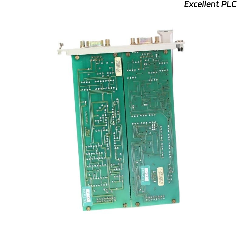
The Honeywell 10004/H/F communication module is used in HC900 / TDC / Experion PKS systems to manage data exchange between controllers, I/O modules, and supervisory systems.
Symptoms of failure:
-
Communication with the system fails.
-
Module reports fault codes on display or SCADA interface.
-
LEDs may indicate PWR: green, COM: off/blinking red, FAULT: solid red.
2️⃣ Initial Observation
| Symptom | Details |
|---|---|
| Communication failure | Controller/SCADA cannot exchange data with module |
| LED Status | PWR green, COM off/blinking, FAULT red |
| Fault code | Displayed on module or SCADA software (note exact code) |
| Environmental | Temperature, humidity, vibration normal |
⚠️ Important: Always record the exact fault code, as it helps identify whether the issue is power, wiring, configuration, or internal hardware.
3️⃣ Step 1 — Power & Physical Inspection
| Action | Checkpoints | Notes |
|---|---|---|
| Verify module voltage | 24 VDC ±10% | Measure at terminals with multimeter |
| Inspect connectors | Bent pins, oxidation, loose fit | Clean contacts if minor corrosion |
| Check LEDs | PWR, COM, FAULT | Verify behavior matches manual |
Observation: Power OK → continue to communication checks.
4️⃣ Step 2 — Fault Code Analysis
-
Consult Honeywell documentation for 10004/H/F fault codes.
-
Typical codes indicate:
-
Bus timeout or link error
-
Incorrect node address or duplicate address
-
Internal communication board fault
-
Recommendation: Record code and compare to manual troubleshooting table.
5️⃣ Step 3 — Communication Cabling
| Action | Checkpoints | Notes |
|---|---|---|
| Inspect bus or network cable | Check for breaks, twisted pairs, damaged insulation | Replace cable if needed |
| Verify connectors | Firm, clean, proper type | Ensure correct termination resistors (typically 120 Ω for RS-485) |
| Test network continuity | Using multimeter or cable tester | Confirm no short circuit or open lines |
Field insight: Even a single miswired or oxidized cable can trigger communication failure and fault codes.
6️⃣ Step 4 — Configuration Verification
-
Confirm module node address is unique on the network.
-
Check baud rate / communication protocol matches controller settings.
-
Reinitialize the module from SCADA or engineering tool to see if fault clears.
7️⃣ Step 5 — Module Self-Test
-
Power-cycle the module.
-
Observe LED sequence and COM activity.
-
If COM remains off and FAULT persists → likely internal module issue.
-
If available, use Honeywell maintenance software to run self-diagnostics.
8️⃣ Step 6 — Replacement & Verification
-
Install a known-good 10004/H/F module with the same firmware revision.
-
Power on and verify:
-
PWR LED steady green
-
COM LED blinking normally
-
FAULT LED off
-
-
Reconnect network and monitor communication.
Observation: Successful connection confirms original module is defective.
9️⃣ Preventive Measures
| Task | Frequency | Purpose |
|---|---|---|
| Inspect connectors & cables | Every 6 months | Prevent oxidation and loose contacts |
| Verify module configuration | After installation or firmware update | Avoid node conflicts |
| Monitor LED status | Continuous | Early warning of degradation |
| Maintain firmware backups | Scheduled maintenance | Quick recovery after replacement |
🔍 Field Insight
-
65–70% of communication failures in Honeywell 10004/H/F modules are due to power, cabling, or node address conflicts.
-
Internal module faults are less common (~30%) but usually identified by persistent fault codes despite correct power and cabling.
✅ Summary
When a Honeywell 10004/H/F module cannot communicate and shows a fault code:
Recommended workflow:
1. Power & LED check → 2. Fault code analysis → 3. Cable & connector inspection → 4. Configuration verification → 5. Self-test → 6. Replacement if necessary → 7. Preventive maintenance.
Following this method ensures rapid fault isolation and restores system communication reliably.