

Installing the Honeywell 10004/H/F communication module requires attention to physical alignment, proper wiring, and controller configuration. Over the years, I’ve learned that skipping small steps often causes hours of troubleshooting later.
Physical Installation
First, ensure the PLC rack is completely powered down. This module is not hot-swappable; inserting it while powered can freeze the node.
I always inspect the module and backplane fingers. Even minor dust or oxidation can interfere with communication. Insert the module gently until you feel the “click” of full engagement.
-
Avoid installing it next to high-power analog modules—electrical noise can affect the COMMS link.
-
Check grounding continuity; unstable grounding can lead to intermittent communication issues.
Connecting Communication Lines
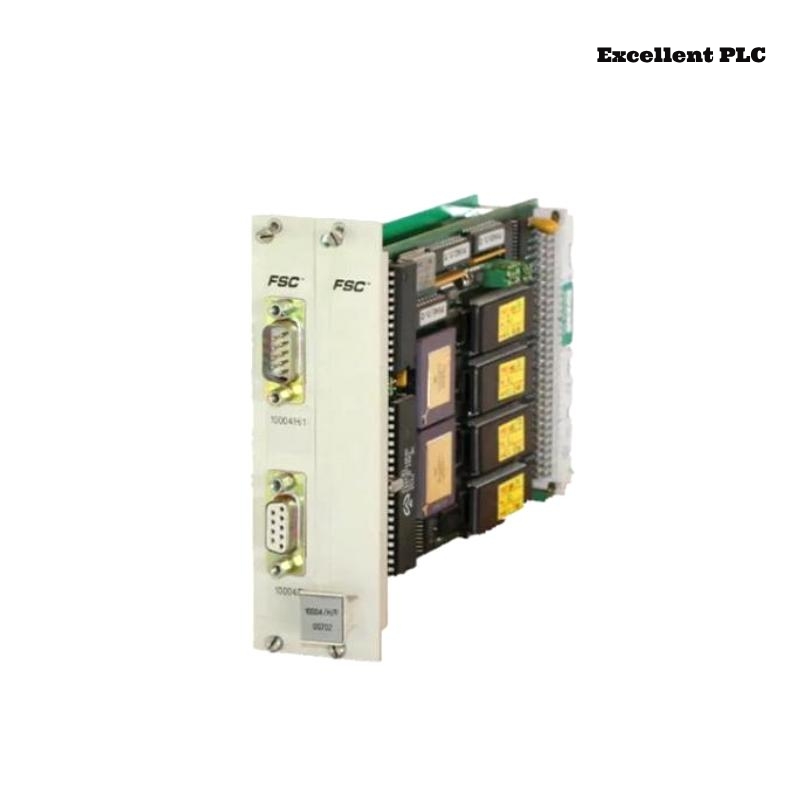
The 10004/H/F module connects via keyed communication ports.
-
Ensure cable shields are grounded only at the cabinet, not at the module.
-
Tighten connector screws to avoid micro-movements.
-
Avoid cable tension or sharp bends.
For replacement cables, connectors, or compatible accessories, I often refer clients to trusted suppliers like ExcellentPLC:
👉 https://www.excellentplc.com/
Field insight: Loose connectors are by far the most common cause of modules appearing “semi-functional.”
Power-Up and LEDs
After powering the rack:
-
LEDs flash briefly for self-test
-
Standby state shows slow blink
-
Active communication is indicated by solid green
If LEDs remain amber, check slot assignment, firmware version, and seating of the backplane connector.
Loading Configuration and Sample Code
Using Honeywell Safety Manager or Experion tools, the module must be assigned the correct slot number and communication mode.
Here’s a small example in pseudo-code showing a basic digital input read and output control:
-
DI_HF_01→ digital input mapped through 10004/H/F -
DO_HF_01→ digital output controlled by HMI/project logic
Practical tip: Test one channel first before scaling to multiple I/O points. This avoids configuration conflicts and prevents system downtime.
Final Validation
-
Verify COMMS LEDs are stable
-
Monitor error counters for 10–15 minutes
-
Gently stress communication cables to ensure connections hold
Following these steps ensures stable operation, reduces repeated troubleshooting, and prevents unnecessary replacement of modules.
References:
-
Honeywell. 10004/H/F Communication Module User Manual, 2019
-
Honeywell. Safety Manager Hardware Installation Guide, 2020