

1️⃣ Overview
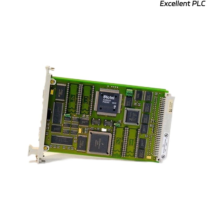
The Honeywell 10012/1/2 Central Processor uses a flash memory module to store system firmware, configuration, and control logic. Proper installation ensures reliable operation and firmware retention during power cycles.
This guide covers step-by-step installation, safety precautions, and verification procedures.
2️⃣ Safety Precautions
-
Power down the HC900 / TDC / Experion system completely.
-
Disconnect AC/DC power supply to the CPU module.
-
Wear ESD protection (wrist strap or ESD mat).
-
Ensure ambient temperature is within 20–25°C.
-
Handle flash memory by edges only, avoid touching PCB traces.
⚠️ Warning: Installing flash memory with system powered on can corrupt firmware or damage the CPU board.
3️⃣ Required Tools
-
Honeywell-approved flash memory module for 10012/1/2 CPU
-
ESD wrist strap
-
Small flathead screwdriver (optional for module latch)
-
Multimeter (for power verification if needed)
4️⃣ Step-by-Step Installation
Step 1 — Remove CPU Module (if installed)
-
Disconnect all network and I/O cables.
-
Release CPU module from rack latch.
-
Place module on ESD-safe surface.
Step 2 — Access Flash Memory Slot
-
Locate the flash memory slot on the CPU PCB (consult CPU diagram/manual).
-
Open the protective cover if present.
-
Ensure slot pins are clean and free from dust or debris.
Step 3 — Insert Flash Memory Module
-
Align the gold edge contacts of the flash memory with the CPU slot.
-
Slide module firmly but gently into the slot until fully seated.
-
Lock any latches or retention clips.
Tip: Do not force the module; incorrect alignment can bend pins.
Step 4 — Reinstall CPU Module
-
Insert CPU module back into the rack.
-
Ensure proper alignment with the backplane connector.
-
Secure latches and reconnect I/O and communication cables.
Step 5 — Power On & Verification
-
Restore power to the system.
-
Observe PWR and RUN LEDs on CPU module:
-
PWR: solid green
-
RUN: blinking green (normal operation)
-
-
Use engineering workstation or SCADA tool to verify flash memory presence:
-
Confirm firmware version
-
Ensure configuration data is recognized
-
No fault codes related to memory
-
5️⃣ Troubleshooting
| Symptom | Possible Cause | Action |
|---|---|---|
| CPU does not boot | Flash not seated correctly | Re-seat flash module |
| Memory fault code displayed | Incompatible or defective flash | Replace with approved module |
| LED pattern abnormal | Static discharge or installation error | Power down, reinstall module |
| Firmware not recognized | Wrong module version | Verify part number against CPU revision |
6️⃣ Field Tips
-
Always verify firmware compatibility before installation.
-
Keep spare flash modules in anti-static packaging.
-
Document installation date and firmware version in maintenance logs.
-
Avoid repeated insertions/removals to prevent connector wear.
✅ Summary
Installing a flash memory module in a Honeywell 10012/1/2 CPU involves:
Power down → Access flash slot → Insert module → Reinstall CPU → Verify operation
Following this procedure ensures:
-
Firmware integrity
-
Reliable CPU startup
-
Prevention of memory-related faults