

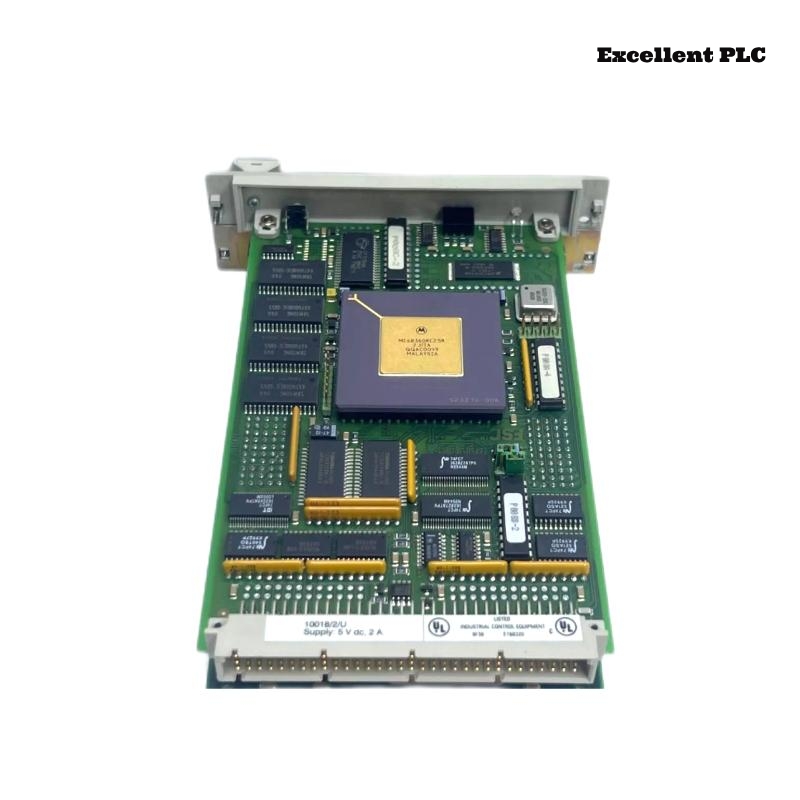
The Honeywell 10018/2/U is a communication module for Safety Manager or Experion systems, allowing reliable data transfer between controller nodes and peripheral devices. Based on field experience, proper installation and initial configuration are crucial to prevent communication faults.
Physical Installation
-
Always power down the PLC rack before handling the module. Hot-insertion may freeze the node or damage internal electronics.
-
Inspect the module’s contacts and backplane connector; Honeywell connectors are precise, and slight misalignment can prevent initialization.
-
Slot positioning matters: keep it away from high-noise analog modules to reduce communication errors.
Tip from experience: A gently seated module that clicks into place usually avoids 90% of communication issues.
Connecting the Communication Cables
-
Attach the communication cables according to system documentation. The 10018/2/U may support redundant network paths.
-
Make sure cable shields are grounded at the cabinet, not at the module.
-
Tighten connector screws; loose cables are a common source of intermittent COMMS errors.
If you need compatible cables or spares, ExcellentPLC provides industrial-grade parts:
👉 https://www.excellentplc.com/
Field insight: Even a perfectly installed module will fail to communicate if the cable is slightly pulled or twisted.
Power-Up and LED Verification
After powering the rack:
-
The module performs a self-test (LEDs flash briefly)
-
Standby LED blinks slowly
-
Active communication is indicated by steady green
Amber or flashing LEDs often indicate slot mismatch, firmware incompatibility, or partially seated connectors.
Configuration and Sample Code
After physical installation, configure the module via Honeywell Safety Manager or Experion tools. Ensure:
-
Correct slot number assignment
-
Communication mode (redundant or non-redundant)
-
Firmware matches the controller node version
Here’s a small example in pseudo-code for reading a digital input and controlling an output through the module:
-
DI_10018_01→ input channel connected via 10018/2/U -
DO_10018_01→ output driven through the module
Practical advice: Start with a single channel test before deploying multiple I/O to ensure communication reliability.
Field Verification
-
Check COMMS LEDs are stable after power-up.
-
Monitor error counters for a few minutes.
-
Test cable stress to ensure connection integrity.
Following these practices prevents most field failures and reduces unnecessary replacement cycles.
References:
-
Honeywell. 10018/2/U Communication Module Installation Manual, 2020
-
Honeywell. Safety Manager System Hardware Guide, 2019