

When I first started working with Schneider’s Modicon TM3 series, I didn’t pay much attention to the small modules that expand the system — until I had to install a TM3XTRA1 Remote Transmitter Module for a remote I/O application. It looked simple, but I quickly learned that getting it to work smoothly required attention to wiring, addressing, and signal integrity.
Here’s how I went through the process step by step — what worked, what didn’t, and what I’d recommend to anyone setting it up for the first time.
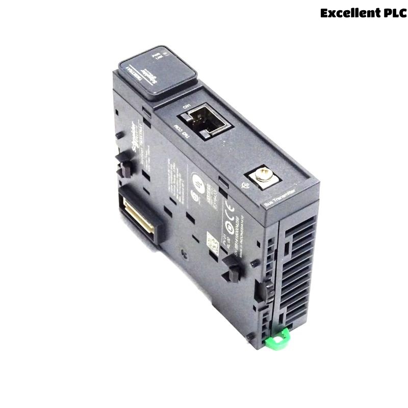
Step 1: Understanding the Role of TM3XTRA1
The TM3XTRA1 module is part of the Modicon TM3 expansion system used with M221, M241, and M251 PLCs.
Its main function is to extend I/O over a remote distance using a TM3 bus expansion cable (usually connected to a TM3XTRA2 or TM3XTRE transmitter/receiver pair).
Think of it like this:
-
The TM3XTRA1 sends data and power from the main PLC rack.
-
The TM3XTRA2 or TM3XTRE receives it on the remote end.
Together, they act as a bridge, allowing additional I/O modules to be installed far from the main controller — great for large machines or split panels.
Step 2: Planning the Installation
Before touching any cables, I sketched out the connection layout.
The TM3XTRA1 needs to be placed at the end of the local TM3 I/O chain, because it essentially “terminates” the local bus and starts the remote link.
My setup looked like this:
I also made sure:
-
The TM3 bus cable (part no. TM3ACC005 or TM3ACC006) matched the required distance.
-
The remote rack had its own 24VDC power source to ensure stable operation.
Step 3: Mounting and Wiring
The TM3 modules are DIN-rail mounted, so the mechanical part is straightforward.
But the wiring sequence is important for signal reliability:
-
Power off the PLC completely.
-
Snap the TM3XTRA1 onto the DIN rail next to the last local I/O module.
-
Connect the bus ribbon cable between TM3XTRA1 and the previous I/O module — make sure it’s firmly seated.
-
Plug the TM3 extension cable into the RJ45-style port on the TM3XTRA1.
-
Route the cable carefully to avoid power wiring or motor lines — noise can cause intermittent disconnections.
💡 Tip from experience:
Once, I had intermittent signal loss during testing. The issue turned out to be an unshielded cable running too close to a variable-frequency drive line. Rerouting and grounding fixed it immediately.
Step 4: Connecting the Remote End
At the remote panel, I mounted a TM3XTRA2 receiver module, connected the same type of cable, and attached the additional I/O modules.
The remote section needs its own 24VDC supply, because the TM3XTRA1 only transmits communication signals, not power over long distances.
Without local power, the remote modules simply don’t initialize.
✅ Checklist:
TM3XTRA1 and TM3XTRA2 are connected using a proper TM3 bus extension cable.
Remote rack powered by a separate 24VDC PSU.
Ground both sides to the same potential to avoid signal offset.
Step 5: Software Configuration
Once the wiring was complete, I opened EcoStruxure Machine Expert (SoMachine) to configure the system.
Here’s the sequence I used:
-
Add a new device → select your controller (e.g., M221 or M241).
-
Under the I/O configuration tree, add TM3XTRA1 as the last local module.
-
Then add the remote side modules (AI, AO, DI, DO) in order, following your physical installation.
-
The software automatically recognizes the TM3XTRA1 → TM3XTRA2 link.
When I downloaded the program and switched to “Online” mode, all remote I/O channels appeared correctly under the PLC’s configuration tree — a good sign everything was synchronized.
Step 6: Testing Communication
To make sure everything worked, I performed a few quick tests:
-
Forced a digital output from the remote I/O (through TM3XTRA2) — the output LED lit immediately.
-
Read analog input values — they refreshed in real time.
-
Disconnected the extension cable — PLC immediately showed “Remote I/O link lost” fault.
All this confirmed the TM3XTRA1 link was reliable.
Step 7: Troubleshooting Common Problems
Here are the main issues I’ve encountered with TM3XTRA1 and how I fixed them:
| Problem | Possible Cause | Solution |
|---|---|---|
| Remote I/O not detected | Cable not fully seated or wrong order | Reconnect, check sequence (must end with TM3XTRA1) |
| Random disconnections | Electromagnetic noise | Use shielded cable and ground both ends |
| Power LEDs off on remote | No local 24V supply | Provide separate power to TM3XTRA2 and I/O modules |
| Data delay or flickering inputs | Long cable route near power lines | Re-route cable, maintain distance from high-current wiring |
🧠 Pro Tip:
Always check that the TM3XTRA1 firmware version matches your PLC’s firmware compatibility list in Schneider’s documentation — mismatches can cause random behavior during startup.
Step 8: Maintenance and Field Experience
After several installations, I’ve noticed that the TM3XTRA1 modules are very stable once properly grounded.
However, avoid frequent plugging/unplugging of the RJ45-type cable; the contacts can loosen over time.
I now label every cable and module position inside the cabinet.
It saves hours when troubleshooting later or training new technicians.
Final Thoughts
The Schneider TM3XTRA1 Remote Transmitter Module is a small but powerful way to extend I/O over distance without needing a full secondary PLC.
If you take the time to plan cable routing, supply clean power, and configure your I/O tree carefully, it works flawlessly — even in noisy industrial environments.
From my own projects, the biggest takeaway is this:
“Don’t treat TM3XTRA1 as just another module — treat it as the backbone of your remote I/O network.”