

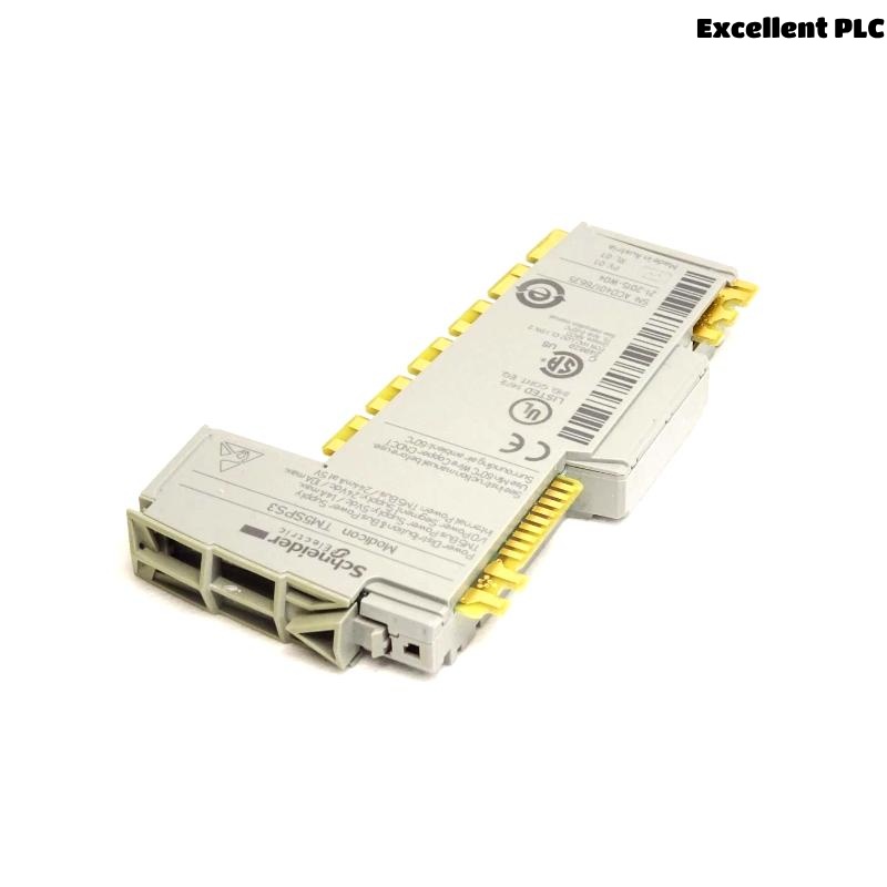
When I first worked on a Modicon TM5 I/O system, one of the key components I dealt with was the Schneider TM5SPS3 Power Distribution Module.
This small yet critical unit ensures reliable 24VDC power delivery to TM5 extension modules.
Here’s how I installed, configured, and tested it during an actual automation panel build.
Step 1: Understanding What the TM5SPS3 Does
Before using it, I needed to understand its purpose clearly.
The TM5SPS3 isn’t just a simple power input — it’s a power distribution module that supplies and regenerates the 24VDC field and logic power for a TM5 I/O island.
It has two independent power segments:
-
Logic Power (24V L+ and 0V L-) → for the controller and internal bus.
-
Field Power (24V F+ and 0V F-) → for sensors, actuators, and I/O modules.
Essentially, the TM5SPS3 acts as a power injection and isolation point that allows the I/O system to extend while maintaining electrical separation between logic and field voltages.
Step 2: Mounting and Installation
In my project, the TM5 modules were DIN-rail mounted inside a control cabinet alongside a TM5 CPU and several I/O slices.
Here’s how I installed the TM5SPS3 safely and correctly:
-
Power down all equipment before mounting the module.
-
Snap the TM5SPS3 onto the DIN rail next to the last I/O module of the first power segment.
-
Ensure the TM5 bus connectors on both sides align and engage properly — this is critical, as power and communication are passed through these connectors.
-
Tighten any retaining clips or locks if your mounting rail requires it.
⚙️ Tip: Keep at least 50 mm of clearance above and below the module for proper airflow. TM5 systems can run warm under heavy load.
Step 3: Wiring the Power Supply
Once the module was secured, I proceeded to wire it up.
The TM5SPS3 front connector block is labeled clearly:
-
L+, L– — logic power input (24VDC).
-
F+, F– — field power input (24VDC for sensors/outputs).
-
0V COM — common reference ground.
My wiring sequence was as follows:
-
From the 24VDC power supply, connect +24V to L+ and 0V to L–.
-
Connect another set of +24V and 0V lines (or the same supply, depending on your design) to F+ and F–.
-
Use shielded cables or twisted pairs for the 24VDC lines if the control panel has high EMI noise.
-
Ensure that wire ferrules are properly crimped before insertion into the removable connector block.
⚠️ Warning: Never reverse L+ and L– — I once did during an early test, and the module immediately cut power to downstream I/O. The TM5SPS3 includes short-circuit and reverse polarity protection, but repeated mistakes can shorten its lifespan.
Step 4: Checking Power Distribution
After wiring, I powered on the cabinet and monitored the module’s status LED indicators.
-
A steady green LED indicated that both logic and field power were correctly distributed.
-
If the LED flashed or stayed off, it meant one of the power inputs was missing or undervoltage.
Using a multimeter, I measured:
-
24.1V between L+ and L–
-
24.0V between F+ and F–
Both readings confirmed stable voltage at the terminals.
Next, I checked downstream modules (digital inputs and outputs) — their power LEDs were on, confirming that the TM5SPS3 was correctly feeding the I/O bus.
Step 5: Extending the TM5 I/O Island
One of the main reasons to use TM5SPS3 is to extend a TM5 island when power load increases.
In this project, we had 24 digital outputs drawing around 1.8A total.
By inserting the TM5SPS3 between groups of modules, I created two independent power zones:
-
Zone 1: 16 digital inputs and CPU logic.
-
Zone 2: 24 digital outputs powered through TM5SPS3.
This setup ensured that heavy output currents didn’t affect logic or communication stability.
Step 6: Functional Testing
With power segments separated, I simulated full load:
-
Energized all output channels simultaneously.
-
Measured voltage drop across the F+ terminals — less than 0.2V, well within spec.
-
Verified that logic remained stable (no CPU reset, no communication fault).
This confirmed the TM5SPS3 was distributing power efficiently.
Step 7: Maintenance and Best Practices
After several installations, here are some lessons I’ve learned about the TM5SPS3:
-
Label each power segment clearly — maintenance technicians need to know which 24V source feeds which module group.
-
Use a separate DC fuse or circuit breaker for each TM5SPS3 input to simplify troubleshooting.
-
Periodically check terminal tightness; vibration or temperature cycles can loosen field wiring over time.
-
If the LED shows a fault, always check both L and F lines — a loose field connection can appear like a total module fault.
Step 8: Integrating in EcoStruxure Machine Expert
Although the TM5SPS3 doesn’t require software configuration, it appears in the hardware layout within EcoStruxure Machine Expert (or SoMachine).
Adding it in the configuration ensures proper current budget calculation and system validation.
Steps I followed:
-
Open the hardware catalog and insert TM5SPS3 into the bus position.
-
Define the power supply parameters (24VDC, 3A max).
-
Verify that downstream modules’ total current doesn’t exceed TM5SPS3 rated limits.
Once added, the software automatically updates the total power consumption of the TM5 I/O system.
Final Thoughts
The Schneider TM5SPS3 Power Distribution Module might seem simple, but it plays a crucial role in maintaining system stability, safety, and expandability.
By properly wiring, isolating power zones, and regularly checking load conditions, this module can operate flawlessly for years in industrial environments.
From my field experience, taking the time to plan your power segmentation strategy around TM5SPS3 modules always pays off — fewer voltage dips, better protection, and cleaner diagnostics.