

1. Incident Overview
-
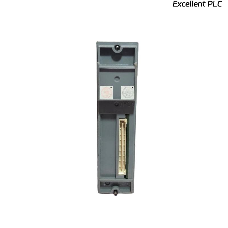
Device: Yokogawa EB402 Bus Interface Module
-
Issue Type: Human error (incorrect wiring and module configuration)
-
Location: Production Line 3, I/O Control Cabinet
-
Duration: 1 hour downtime
-
Root Cause: Incorrect wiring and faulty configuration during maintenance
-
Result: Loss of communication between field devices and control system
This incident explores a failure scenario caused by human error during module wiring and configuration. It provides insight into diagnosing such errors and recovering the system to normal operation.
2. Incident Details
Event Summary
-
Date: 2025-07-15
-
Time: 09:30 AM — Maintenance crew performs wiring update for I/O rack.
-
Symptoms:
-
EB402 module fails to initialize after installation.
-
Bus communication timeouts raised by the system.
-
LEDs on the EB402 remain off, indicating no power or initialization failure.
-
Root Cause Analysis
-
Human Error: During routine maintenance, the wiring was connected to the wrong power input terminal. The technician mistakenly swapped the 24V DC input with the ground terminal, causing incorrect voltage input to the EB402.
| Time | Event |
|---|---|
| 09:32 | Initial power-up after wiring |
| 09:34 | LEDs fail to illuminate on EB402 |
| 09:36 | Communication failure alarm triggered |
| 09:45 | Technician investigates and identifies incorrect wiring |
3. Diagnosing the Fault
Step 1: Check LED Status
-
Symptoms: The green LED on the EB402 should illuminate when the module is powered up correctly. If the module does not display any LEDs, it’s likely not receiving proper power.
Solution:
Use a multimeter to check voltage levels at the module’s power input. Verify that the 24V DC input is connected correctly.
Step 2: Correct Wiring Check
-
Issue Found: Upon inspection, it was confirmed that the 24V input was connected to the ground terminal, while the ground was mistakenly wired to the 24V input terminal.
Solution:
-
Disconnect the module from the power source immediately.
-
Correct the wiring to match the correct 24V DC and ground terminals.
-
Reconnect the system and power up.
4. Recovery and Resolution Steps
Step 1: Reconnect Power and Reset the System
-
After correcting the wiring, power on the system again.
-
Ensure that the 24V DC input is connected to the appropriate terminal, and the ground is properly wired.
Step 2: Verify Initialization
-
Observe the LED indicators on the EB402. The green LED should illuminate within seconds after power-up.
-
Verify the system’s bus communication by checking if the EB402 can successfully establish communication with the connected field devices.
Step 3: Perform Full System Check
Once the module is functional, perform a full system check to ensure all connections and configurations are correct. Test each I/O channel to confirm proper functionality.
5. Preventive Measures to Avoid Human Error
To prevent such issues from occurring in the future, the following steps are recommended:
1. Double-Check Wiring Diagrams
Before any maintenance work, always refer to the correct wiring diagrams and configuration manuals for every module. This ensures that the technician follows the correct procedures and wiring layout.
2. Proper Training and Certification
Ensure that all technicians are adequately trained in the installation and maintenance of critical system modules. Regular refresher courses can prevent mistakes.
3. Implement a Wiring Inspection Process
Introduce a wiring inspection checklist for each installation or maintenance session. This checklist should be signed off by both the technician and supervisor before proceeding to the next step.
4. Use Wiring Markers
Label all terminals with clear markers indicating their functions (e.g., “24V Input,” “Ground,” “Bus,” etc.). This can help prevent confusion during installation or maintenance.
6. Conclusion
This incident highlights the significant impact of human error on system functionality. By simply swapping the wiring of the power input and ground, the EB402 bus interface module failed to initialize, causing communication breakdown. However, after identifying the root cause and performing the appropriate corrective actions, the system was restored.