

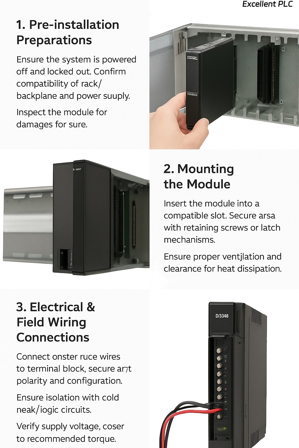
1. Pre‑installation Preparations
-
Ensure the system is powered off and locked out to avoid electrical hazards.
-
Confirm that the rack/backplane and power supply meet the module’s requirements (voltage, current, environmental conditions).
-
Inspect the DI3301S2 module for any physical damage (bent pins, cracked case) before insertion.
-
Check that the firmware of the system (controller, backplane) is compatible with the DI3301S2 module.
2. Mounting the Module
-
The module is designed for insertion into a compatible rack/backplane slot. Ensure the slot is empty and that the bus‑connector is clean and undamaged.
-
Insert the module carefully: align with the guide rails or slots, slide in until the module engages the bus connector firmly.
-
Secure the module if there are retaining screws or latch mechanisms.
-
Ensure proper ventilation around the module and maintain the manufacturer’s recommended clearance for heat dissipation.
3. Electrical & Field Wiring Connections
-
Connect the field input wires (from sensors, switches, etc.) to the terminal block of the DI3301S2. Confirm correct polarity and configuration (sink/source, dry/wet contacts) as specified by your system design.
-
Ensure isolation between field wiring and logic circuits (the module supports high galvanic isolation).
-
Verify that the supply voltage (e.g., 24 V DC) is within the module’s acceptable range and that current load is within specification.
-
Tighten terminal screws to the recommended torque. Avoid loose or over‑tightened connections which may cause signal integrity or safety issues.
-
If applicable, connect the module’s diagnostics or status LEDs to view initial module health.
4. Configuration & Commissioning
-
Power up the rack/system. Monitor the module’s status LEDs (if present) for normal operation indication.
-
Using the system configuration software (e.g., TriStation or equivalent), verify that the DI3301S2 is recognized by the system and mapped correctly to the correct rack and slot address.
-
Configure the input channel types, filtering settings, and diagnostics thresholds as required by your safety instrumented system.
-
Perform a functional test on each input channel: actuate each sensor/switch and validate that the system sees the input change correctly.
-
Review and log module diagnostic messages: check for open‑circuit, short‑to‑ground, or other wiring fault indications.
5. Post‑Installation Checks & Maintenance
-
After installation and commissioning, periodically inspect wiring connections, terminal blocks, ventilation, and module status.
-
Use diagnostics to detect early signs of degradation (for example, increased channel fault counts, abnormal LED statuses).
-
Maintain firmware and software versions in accordance with manufacturer guidance to ensure compatibility and security.
-
If the module needs replacement, follow the hot‑swap procedure (if supported) and ensure that system state is maintained and that safety integrity is not compromised.
Important Safety & Best Practice Notes
-
Always comply with local electrical codes and safety regulations when installing or servicing safety‑instrumented modules.
-
Ensure that any removal or insertion of modules happens under controlled conditions (rack in a safe state, bus power isolated if required).
-
Keep spare modules and approved components on hand, and document module serial numbers, firmware versions and installation dates for traceability.
-
Maintain the module in an environment free of excessive vibration, moisture, dust accumulation and temperature extremes beyond the module’s specification.