

The 1771-IR/D is a 32-channel DC input module for PLC-5 systems. It reads discrete DC signals and is commonly used for switches, sensors, and field interlocks. Proper installation ensures reliable operation and accurate input detection.
Step 1: Physical Installation
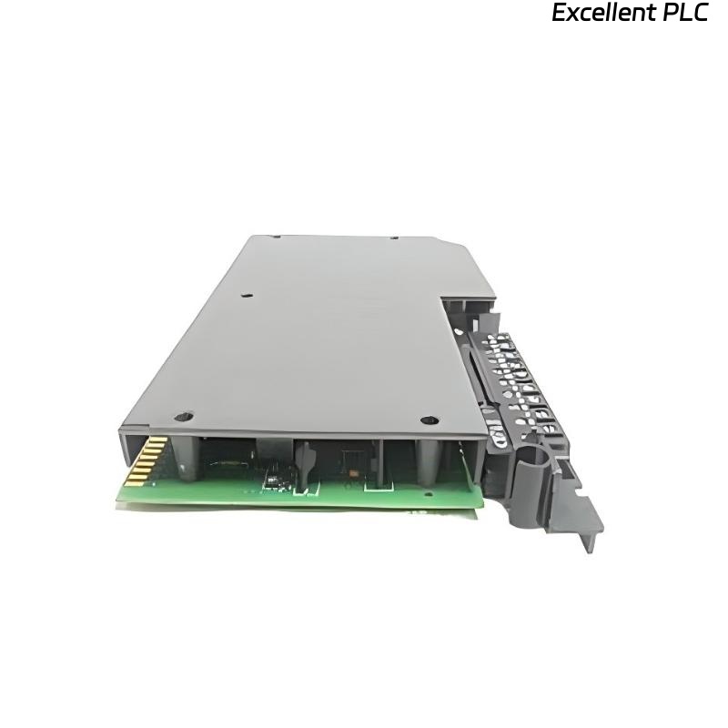
Mount the 1771-IR/D in a 1771 PLC chassis. Ensure the module is securely seated in its slot on the backplane. Loose installation can lead to intermittent input readings.
Tips from the field:
-
Avoid placing the module next to high-power AC modules to reduce electrical noise.
-
Check that the backplane fingers are clean and free of corrosion before insertion.
Step 2: Wiring the DC Inputs
-
Each input channel accepts 10–30V DC signals.
-
Connect the positive (+) DC line to the corresponding input terminal.
-
Connect the common return (COM) to the module’s negative terminal.
-
Use shielded twisted-pair cable for long runs to minimize noise interference.
-
Label wires according to channel number for easier troubleshooting.
Step 3: PLC Configuration in RSLogix 5
-
Open your PLC-5 project.
-
Add the 1771-IR/D module in the I/O configuration. Assign the correct slot number.
-
Map the inputs to addresses I:slot/0 to I:slot/31. These addresses correspond to the physical wiring on the module.
Step 4: Example Ladder Logic Code
This simple ladder logic energizes an output when the start button is pressed and de-energizes it when the stop button is pressed. You can expand the logic for multiple inputs and interlocks.
Step 5: Testing
-
Power up the chassis and observe the module LEDs. Each LED should light when the corresponding input is energized.
-
Monitor input addresses in RSLogix 5 to confirm correct signal reception.
-
Test the ladder logic response to ensure the PLC reacts as expected to field inputs.
Field note: Always verify polarity and voltage before connecting field devices. Reversing polarity can damage the module.
References:
-
Rockwell Automation. 1771-IR/D DC Input Module User Manual, 2019.
-
Rockwell Automation. RSLogix 5 Programming Manual, 2018.