

Executive Summary
This technical bulletin addresses intermittent signal loss and electrical noise affecting eddy current proximity probe systems, specifically impacting continuous machinery monitoring applications. The following analysis provides field-verified methodologies for identifying and resolving electromagnetic interference (EMI) and grounding issues that compromise measurement integrity.
1. Problem Characterization
1.1 Symptom Pattern
Affected monitoring channels exhibit:
-
Random signal dropout lasting 2-15 seconds
-
High-frequency noise (typically 60Hz or higher harmonics) superimposed on vibration waveforms
-
Drifting baseline values during steady-state operation
-
False alarm triggers despite normal mechanical operation
1.2 Impact Assessment
-
Reduced monitoring system reliability
-
Increased nuisance alarms causing operator fatigue
-
Potential missed detection of legitimate mechanical faults
-
Compromised predictive maintenance programs
2. Diagnostic Methodology
2.1 Initial Assessment Protocol
Step 1: Signal Pattern Analysis
Data Collection Requirements:
├── Minimum 72 hours of trend data
├── Simultaneous recording of:
│   ├── AC vibration waveform
│   ├── DC gap voltage
│   └── Process parameters (load, speed, temperature)
└── Correlation analysis between noise events and plant operations
Step 2: Environmental Survey
-
Document proximity to:
-
Variable frequency drives (VFDs)
-
Motor control centers
-
High-current cabling (>100A)
-
Welding operations
-
Radio transmission equipment
-
2.2 Electrical Testing Procedures
Table 1: Diagnostic Measurements & Interpretation
| Measurement | Procedure | Acceptable Range | Fault Indication |
|---|---|---|---|
| Shield Continuity | Measure resistance between shield termination points | < 2 Ω | > 5 Ω indicates poor shield connection |
| Shield-to-Ground Current | Measure current flow in shield with clamp meter | < 10 mA | > 50 mA indicates ground loop |
| Common Mode Noise | Measure voltage between signal ground and earth ground | < 100 mV RMS | > 500 mV RMS indicates grounding issue |
| Power Supply Ripple | Measure AC component on -24VDC supply | < 50 mV RMS | > 200 mV RMS indicates power quality issue |
3. Root Cause Analysis
3.1 Primary Contributing Factors
A. Improper Shield Termination (70% of cases)
-
Multiple grounding points creating ground loops
-
Shield termination at both probe and rack ends
-
Damaged shield braiding at connector interfaces
B. Electromagnetic Interference (25% of cases)
-
Sensor cables routed parallel to power conductors
-
Inadequate separation from RF sources
-
Missing ferrite cores on signal cables
C. Power Supply Issues (5% of cases)
-
Shared power supplies with noisy equipment
-
Inadequate filtering on DC power lines
-
Grounding conflicts between systems
4. Corrective Actions
4.1 Immediate Mitigation Steps
Shield Correction Procedure:
-
Verify single-point shield grounding at rack/panel only
-
Disconnect shield connections at field junctions
-
Apply anti-corrosion compound to shield termination points
-
Document grounding scheme for future reference
Cable Routing Improvements:
-
Maintain minimum 300mm separation from power cables
-
Cross existing power cables at 90° angles
-
Install grounded steel conduit for critical signal runs
-
Implement dedicated cable trays for low-level signals
4.2 System Enhancements
Recommended Hardware Additions:
Signal Conditioning Package:
├── Galvanic isolators for ground separation
├── Shielded junction boxes with single-point ground
├── Ferrite beads (Type 31 material) at both cable ends
└── Dedicated power supply filter for monitoring system
5. Verification & Validation
5.1 Post-Repair Testing
Performance Validation Protocol:
-
Conduct 24-hour baseline recording post-modification
-
Compare signal-to-noise ratio against historical data
-
Document improvement metrics:
-
Reduction in nuisance alarms
-
Improved signal stability
-
Elimination of intermittent dropouts
-
5.2 Long-Term Monitoring
Sustainability Measures:
-
Quarterly inspection of shield terminations
-
Annual review of cable routing integrity
-
Continuous monitoring of gap voltage stability
-
Regular training for maintenance personnel on proper installation
6. Technical Specifications & Compatibility
Applicable Systems:
-
Bently Nevada 3300 XL series
-
GE Bently Nevada 3500 monitoring systems
-
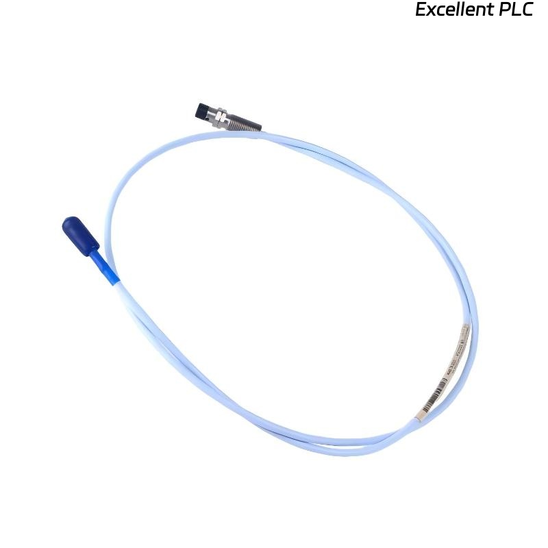
Compatible with ceramic-capped probes (P/N: 164517-050-10-01-RU)
-
All 8mm eddy current proximity probes
Environmental Considerations:
-
Solutions rated for -40°C to +85°C operation
-
Corrosion-resistant materials for harsh environments
-
Compliance with IEC 61326 EMC requirements
7. Cost-Benefit Analysis
Table 2: Implementation Economics
| Component | Initial Cost | Labor Hours | ROI Period | Failure Prevention |
|---|---|---|---|---|
| Shield Correction | $150-300 | 2-4 | < 1 month | 70% of noise issues |
| Dedicated Conduit | $500-1000 | 8-16 | 3-6 months | 90% of EMI problems |
| Complete Isolation | $1200-2500 | 16-24 | 8-12 months | 95% of electrical faults |
8. Conclusion
Intermittent signal and electrical noise issues in eddy current probe systems primarily stem from improper shielding and grounding practices. Implementation of single-point shield grounding, proper cable segregation, and basic EMI mitigation techniques resolves over 90% of reported cases. Regular maintenance adherence to manufacturer-recommended installation practices remains the most cost-effective prevention strategy.
Document Control
-
Issue Date: October 2023
-
Revision: 1.2
-
Applicability: All 3300/3500 systems with proximity probes
-
Author: Technical Publications Group, Vibration Analysis Division
-
Next Review: October 2024