

1. Executive Summary
The Yokogawa CP471 processor module is a critical component in industrial DCS architectures. It manages logic execution, I/O coordination, and communication tasks within the control system. In certain field scenarios, CP471 modules may fail to initiate boot sequences due to insufficient power supply voltage.
This incident report details symptoms, root causes, diagnostics, resolution steps, and preventive actions based on field data collected from a petrochemical facility.
2. System Overview
-
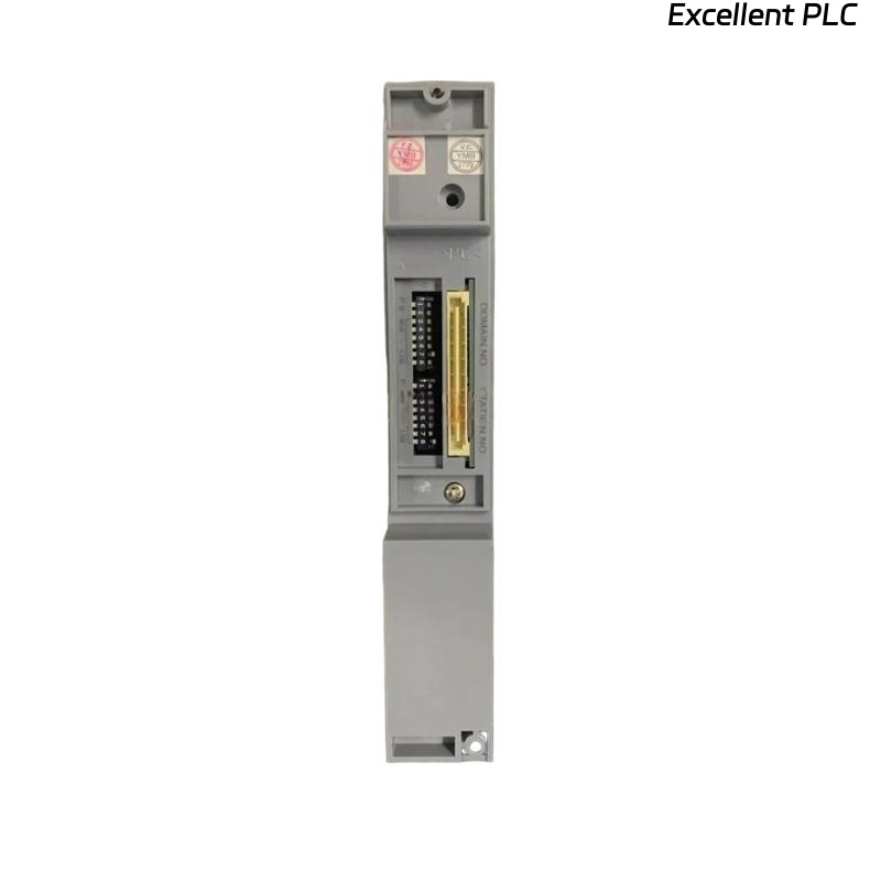
Controller Model: Yokogawa CP471 processor module
-
Application: Distillation tower level and flow control
-
Power Source: 24V DC redundant power supply through isolated PSU module
-
Environmental Conditions: Indoor MCC room, 32°C average, 45% RH
3. Incident Description
Date of Occurrence:
2025-01-07 during night shift startup after scheduled power shutdown.
Observed Symptoms:
Operators reported the following issues:
-
Status LEDs remained OFF during power restoration
-
No boot sequence initiated on CP471 module
-
Remote I/O modules remained in FAIL-SAFE state
-
SCADA station displayed “Controller Offline” alarms
SCADA Alarm Log Example:
Since the CP471 did not start, field devices reverted to predefined failsafe outputs.
4. Diagnostic Procedure
Maintenance engineers followed a structured diagnostic approach:
Step 1 — PSU Voltage Measurement
Using a calibrated multimeter at CP471 power terminals:
Voltage was below CP471’s startup requirement, confirming undervoltage.
Step 2 — PSU Load Verification
Load analysis showed excessive current draw due to simultaneous startup of multiple modules and network devices.
Step 3 — PSU Health Check
-
Capacitor aging observed in DC power module
-
Output ripple measurements exceeded tolerance values
Step 4 — Cabling and Terminal Inspection
-
Slight oxidation detected on DC terminals
-
Minor contact resistance increase (~0.6Ω)
5. Root Cause Analysis
The startup failure was attributed to low DC supply voltage caused by the following combined factors:
✔ Aged PSU Capacitors
Lack of filtering reduced voltage during peak inrush demand.
✔ Simultaneous High Load Startup
Multiple modules drew inrush current, causing temporary voltage collapse.
✔ Terminal Oxidation
Increased resistance further reduced voltage delivered to CP471.
This aligned with the behavior that during normal steady-state operation (no reboot), the power supply remained just above operational threshold, making the issue only visible during restarts.
6. Corrective Measures Implemented
Service technicians executed the following actions:
Hardware Corrections
-
Replaced aging 24V DC PSU module.
-
Cleaned terminals and removed oxidation.
-
Applied corrosion-resistant terminal treatment.
System Adjustments
-
Staggered boot sequence added for network switches and I/O modules.
-
Added buffer capacitor modules to stabilize inrush demand.
-
Verified CP471 cold boot and communication initialization.
After corrective actions, the CP471 successfully completed full startup:
7. Preventive Recommendations
To prevent recurrence, the following actions are recommended:
PSU Maintenance Policies
-
Replace industrial PSU modules every 5–7 years
-
Inspect DC terminals annually for corrosion
-
Measure ripple voltage during preventive maintenance
Electrical Design Improvements
-
Implement staggered power sequencing
-
Install DC buffer capacitors or battery backup modules
-
Monitor DC bus voltage through SCADA
Monitoring & Alarming
Integrate low-voltage thresholds to trigger early warnings such as:
-
UNDER_VOLTAGE_DETECTED
-
PSU_RIPPLE_HIGH
-
INRUSH_CURRENT_EXCEEDED
8. Conclusion
Low supply voltage is a hidden but impactful failure mode for Yokogawa CP471 processor modules. Because the CP471 has strict startup voltage requirements, undervoltage conditions may remain undetected until full system reboots. Through proper PSU maintenance, electrical design adjustments, and monitoring strategies, operators can greatly improve system reliability and reduce startup failures in mission-critical environments.