

Field Incident Description
During extended operation in a high-density control cabinet, operators noticed:
-
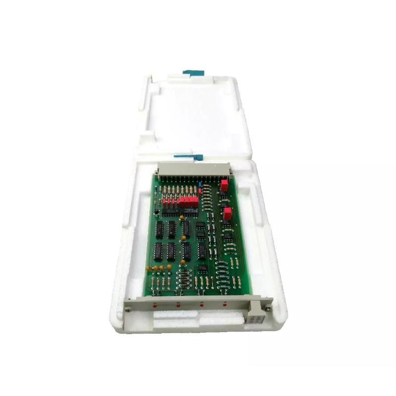
F1201 module felt abnormally hot to the touch
-
Relay activation occasionally delayed or intermittent
-
Cabinet internal temperature rose above normal operating limits
Thermal stress was suspected as the underlying cause of transient failures.
Recognizing Thermal Overload
Key indicators include:
-
Surface temperature above rated maximum (~70°C typical for F1201)
-
Multiple channels showing delayed relay engagement
-
LED indicators dim or flicker under load
-
Intermittent module misbehavior correlated with ambient temperature rise
Thermal stress can degrade relay coil drivers and reduce overall module life.
Step 1 – Measure Module Temperature
– Use infrared thermometer or thermal imaging.
– Record module temperature under full load.
– Compare with cabinet ambient temperature.
Readings showed 15–20°C higher than cabinet ambient near high-current relay outputs.
Step 2 – Evaluate Load Impact
The affected cabinet had multiple inductive loads on adjacent modules, causing:
-
Localized heating near relay coils
-
Voltage drop under high thermal stress
-
Elevated temperature on PCB and driver components
Relay energization delays correlated directly with measured surface temperature.
Step 3 – Identify Contributing Factors
Thermal causes often include:
-
High-duty-cycle relay switching
-
Poor airflow or dense module placement
-
Cabinet ambient temperature above recommended specification
-
Inadequate heat dissipation for driver transistors and coils
Corrective Action
– Add forced ventilation (cabinet fan) near F1201 module.
– Reorganize module placement to reduce heat clustering.
– Reduce duty cycle for non-critical outputs if possible.
– Ensure DC supply within rated voltage and current.
– Consider solid-state relay substitution for high-frequency switching.
After these improvements, module surface temperature dropped by 10–15°C under full load, and relay response returned to normal.
Preventive Engineering Practices
-
Maintain minimum spacing between high-current relay modules.
-
Avoid locating heat-generating devices directly above F1201.
-
Monitor cabinet internal temperature periodically.
-
Schedule maintenance to check for dust accumulation, which can reduce airflow.
Thermal design is critical to preserve relay module reliability in Planar F systems.
Conclusion
Module overheating on the Black Horse F1201 4x Relay Amplifier Module can cause delayed relay activation, intermittent operation, and long-term degradation. Systematic thermal measurements, load analysis, and airflow optimization effectively prevent thermal-related failures and ensure stable operation.