

I’ve worked with Schneider Modicon TSX Micro PLCs for years, and the TSX3705028DR1 remains one of the most reliable mid-range logic controllers for compact automation systems.
Below is a detailed, experience-based tutorial describing how I commissioned and configured this unit from scratch — including hardware setup, wiring, and software initialization.
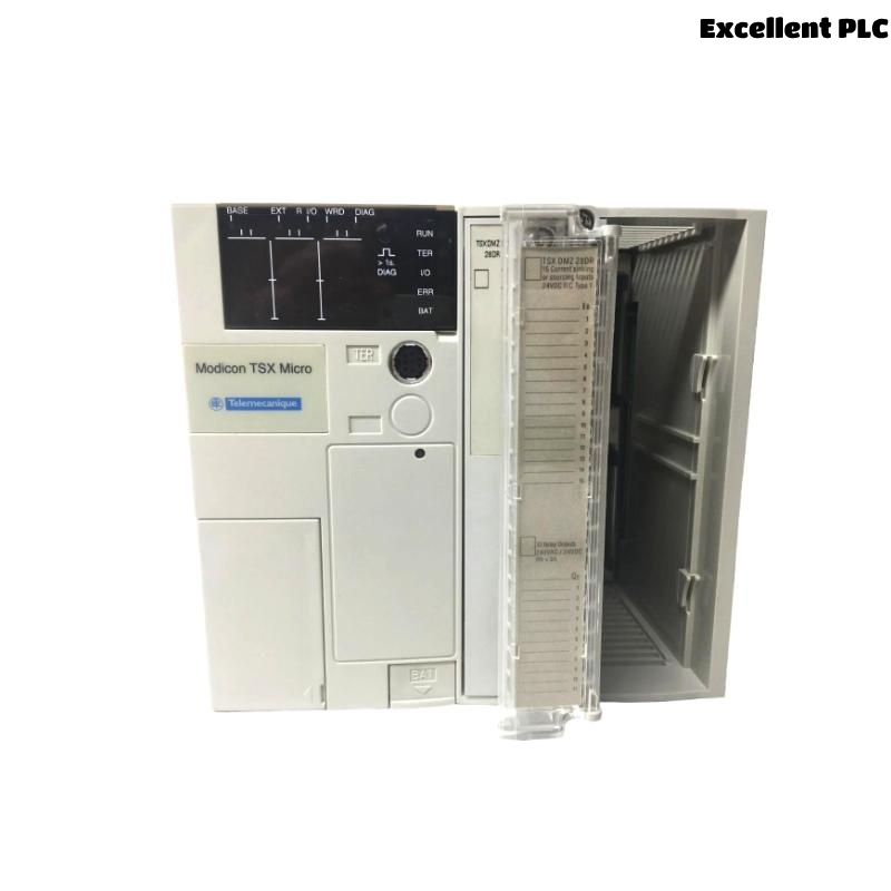
Step 1: Understanding the TSX3705028DR1
The TSX3705028DR1 belongs to Schneider’s Modicon TSX Micro Series, designed for small to medium control systems.
This particular model integrates:
-
16 digital inputs (24V DC)
-
12 relay outputs
-
One RS485 communication port
-
Built-in power supply (100–240VAC)
-
Optional extension slots for analog or communication modules
Before starting, I always verify the module label to ensure it matches the project hardware list — different TSX Micro models may have varying I/O configurations.
Step 2: Power Supply and Initial Inspection
Before installation, I check the unit for any signs of transport damage, especially at the terminal block area.
To power the controller:
-
Connect L (Live) and N (Neutral) to the AC power terminals.
-
Connect PE (Protective Earth) to the grounding bar — this is crucial to prevent communication noise.
-
Verify that your input power is between 100–240VAC, as stated on the label.
Once powered, the RUN/ERR LED sequence should display a brief self-test — if all goes well, the PWR LED remains green, and ERR stays off.
Step 3: Input and Output Wiring
The TSX3705028DR1’s terminals are grouped in blocks — inputs on the left, outputs on the right.
For Digital Inputs (24V DC)
Each input has a common terminal (COM). A typical wiring example:
⚙️ Tip: Always group sensors by function and label cables clearly — the TSX Micro’s terminal spacing is tight, and incorrect wiring can easily cause logic errors during commissioning.
For Relay Outputs
Relay outputs can switch either AC or DC loads, up to 2A per point.
Typical connection:
Make sure to use flyback diodes or RC snubbers on inductive loads to protect relay contacts from arcing.
Step 4: Connecting to Programming Software
To configure the TSX3705028DR1, I used PL7 Micro software (legacy Schneider platform).
Connection Steps:
-
Connect a TSX PCX1031 or TSX PCX3030 cable between the PLC’s TER port (RS485) and your PC’s serial/USB port.
-
Launch PL7 Micro and create a new project.
-
Under Hardware Configuration, select TSX3705028DR1 as the CPU model.
-
Set the communication parameters:
-
Protocol: Unitelway
-
Baud rate: 9600 or 19200 bps
-
Station address: 1 (default)
-
If communication succeeds, the software status bar will display “Connected to PLC”.
Step 5: Writing and Downloading Your First Program
For testing, I wrote a simple logic example to control an indicator lamp when an input sensor activates.
Example Ladder Logic:
Meaning: when input I0.1 is ON, output Q0.1 energizes the relay that drives the lamp.
Then:
-
Compile the program in PL7 Micro.
-
Switch to RUN mode.
-
Download the program to the PLC.
-
Observe that the output LED (Q0.1) turns ON when the input device activates.
Step 6: Testing and Troubleshooting
After downloading, I verify each input/output operation manually:
-
Toggle input devices and confirm the corresponding input LEDs on the PLC turn ON.
-
Activate outputs via the Force function in PL7 to ensure relays click and loads respond.
-
If no response occurs, check for common wiring issues — especially COM terminals mismatched between input groups.
When all I/O behaves correctly, I monitor cycle time and memory usage in the software to confirm stable runtime.
Step 7: Saving and Backing Up the Configuration
Once the system operates as expected:
-
Save the project file locally and on a backup drive.
-
Document firmware version, program revision, and I/O mapping.
-
Label the PLC and cable for future maintenance reference.
🧠 Pro tip: For long-term reliability, add ferrite filters on 24V supply lines and ensure proper cabinet ventilation — TSX Micro controllers run warm under continuous load.
Step 8: Integrating into a Larger System (Optional)
If the TSX3705028DR1 is part of a distributed system, it can communicate with other devices via RS485 Modbus RTU or Unitelway.
Typical applications include:
-
Linking to HMI panels (e.g., Magelis)
-
Communicating with frequency drives
-
Exchanging data with SCADA systems
In PL7, configure communication function blocks such as READ_VAR or WRITE_VAR to exchange data across the network.
Common Issues Encountered
| Symptom | Likely Cause | Solution |
|---|---|---|
| PLC not communicating with PC | Incorrect cable or COM port | Check Unitelway driver settings |
| Inputs not responding | Wrong COM wiring | Verify sensor polarity and 0V common |
| Outputs stuck ON | Relay contact fused | Replace relay or use external interposing relays |
| ERR LED flashing | Configuration mismatch | Re-download correct hardware configuration |
Final Notes
After completing multiple projects with the Schneider TSX3705028DR1, I can confidently say it’s a robust, user-friendly PLC ideal for compact systems.
Its integrated relays simplify wiring, while its modular design allows expansion when needed.
Following a methodical approach — power verification, careful wiring, and proper communication setup — ensures a smooth start-up and long-term stability.