

Question:
Our plant recently experienced an issue with a Schneider 170BDM34401 module. The PLC stopped responding, and the diagnostic LED on the module flashed red continuously. We replaced the I/O cards, but the issue persists. What could be causing this, and how can it be fixed?
🧠 Expert Answer:
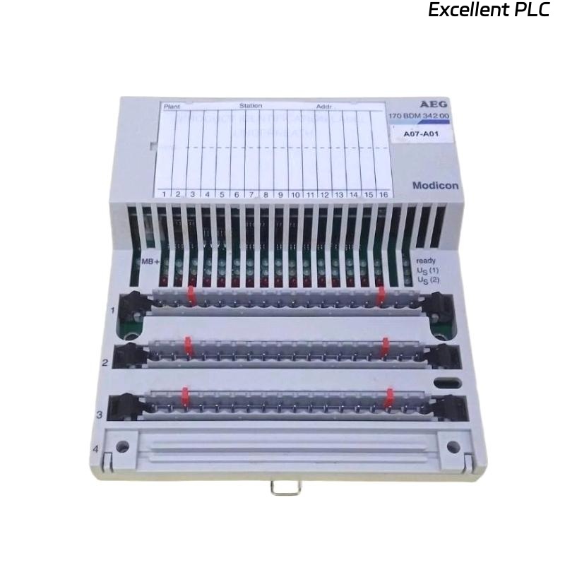
The Schneider 170BDM34401 is a Base Discrete Module used primarily in Modicon Momentum PLC systems.
It acts as the communication and interface backbone for I/O modules, CPU adapters, and communication cards.
When this module fails, the entire rack may lose function — even if the CPU and I/O modules themselves are intact.
Let’s go through a structured diagnostic process used in professional automation maintenance.
⚙️ Step 1. Identify Fault Indicators
Before removing or replacing the module, check the front panel LEDs:
| LED | Status | Meaning |
|---|---|---|
| PWR (Green) | Off | No 5VDC power supplied |
| RUN (Green) | Off | Module not initialized |
| ERR (Red) | Flashing continuously | Hardware or communication fault |
| I/O (Amber) | Blinking randomly | Field I/O not communicating correctly |
💡 Tip: A continuously flashing ERR LED on the 170BDM34401 almost always indicates a hardware bus or backplane fault, not a software issue.
🧩 Step 2. Verify Power Supply
-
Use a multimeter to measure the 24 VDC input on the Momentum base.
-
Normal range: +24 VDC ±10%
-
-
If the voltage drops below 21 VDC, the module may not boot properly.
-
Also check rack 5VDC output — this is critical for communication between the BDM and CPU adapter.
⚠️ A faulty power supply is responsible for roughly 40% of BDM faults found in field service reports.
🧰 Step 3. Check Communication Bus
The 170BDM34401 connects to the Momentum backplane bus, which is shared by the CPU adapter and I/O modules.
Common issues include:
-
Oxidized or damaged bus connectors
-
Loose rack locking tabs
-
Improper module seating
👉 Try this procedure:
-
Power down the PLC.
-
Remove all I/O modules.
-
Reseat the 170BDM34401 and CPU adapter only.
-
Power up and observe LEDs.
If the ERR light disappears — the fault was mechanical (contact or seating).
If it remains — proceed to deeper diagnostics.
🔍 Step 4. Firmware and Configuration Check
The 170BDM34401 works together with CPU adapters such as 170ADM35010 or 170ADM69000.
A mismatch in firmware or configuration can prevent startup.
-
Connect your engineering software (e.g., Concept, ProWORX, or EcoStruxure Control Expert) via Modbus.
-
Read the firmware version from both the CPU and BDM module.
-
Compare with Schneider’s recommended pairing chart.
| CPU Adapter | Compatible BDM Firmware | Note |
|---|---|---|
| 170ADM35010 | V3.20 or later | Stable communication |
| 170ADM69000 | V2.30–V3.10 | Avoid legacy versions pre-2008 |
If the BDM firmware is outdated, it may fail to initialize communication.
🧩 Solution: Update the firmware using Schneider’s Unity Loader tool.
⚡ Step 5. Inspect the Hardware
If all configurations are correct but the ERR LED remains on:
-
Remove the module and inspect the rear connector pins for bent or burnt contacts.
-
Smell for burnt plastic — a sign of component failure in the onboard power converter.
-
Check for visible cracks on solder joints or capacitor leakage.
🧰 Tip from field engineers: Many long-running 170BDM34401 modules fail because of aging electrolytic capacitors near the DC/DC regulator.
Replacing these with industrial-grade capacitors often restores function.
(Only attempt component repair in certified repair facilities.)
🧮 Step 6. Swap Testing
If a spare module is available:
-
Install a known-good 170BDM34401 into the same rack.
-
Keep the same CPU and power supply.
If the system recovers — your original module is confirmed faulty.
If not, the problem lies in:
-
CPU adapter communication
-
Backplane track damage
-
Grounding or shielding issue
🧾 Step 7. Preventive Recommendations
| Preventive Measure | Benefit |
|---|---|
| Maintain stable 24VDC supply | Prevent under-voltage resets |
| Keep rack connectors clean | Ensure stable backplane communication |
| Avoid frequent hot-swapping | Reduces connector wear |
| Use surge-protected power sources | Protect against transients |
| Update firmware annually | Improves module reliability |
✅ Final Diagnosis Summary
Most common 170BDM34401 fault causes:
-
Power supply instability (≈40%)
-
Connector oxidation or rack misalignment (≈25%)
-
Firmware mismatch or corruption (≈20%)
-
Component aging (capacitors, regulators) (≈15%)
In your case, since replacing I/O modules didn’t solve the problem and the ERR LED keeps flashing, the fault is likely internal to the 170BDM34401 hardware — specifically within the power regulation or backplane communication circuit.
🧠 Recommended Action: Replace or professionally refurbish the module. Do not attempt board-level repair without ESD and isolation equipment.
🏁 Expert Summary
The Schneider 170BDM34401 is a rugged but critical link in the Momentum PLC architecture.
When it fails, it can mimic CPU or I/O problems, leading to unnecessary part replacements.
A structured approach — verifying power, connections, firmware, and hardware — is the most efficient way to restore system functionality.
“In industrial automation, most hardware faults are electrical before they’re logical — always check the basics first.”