

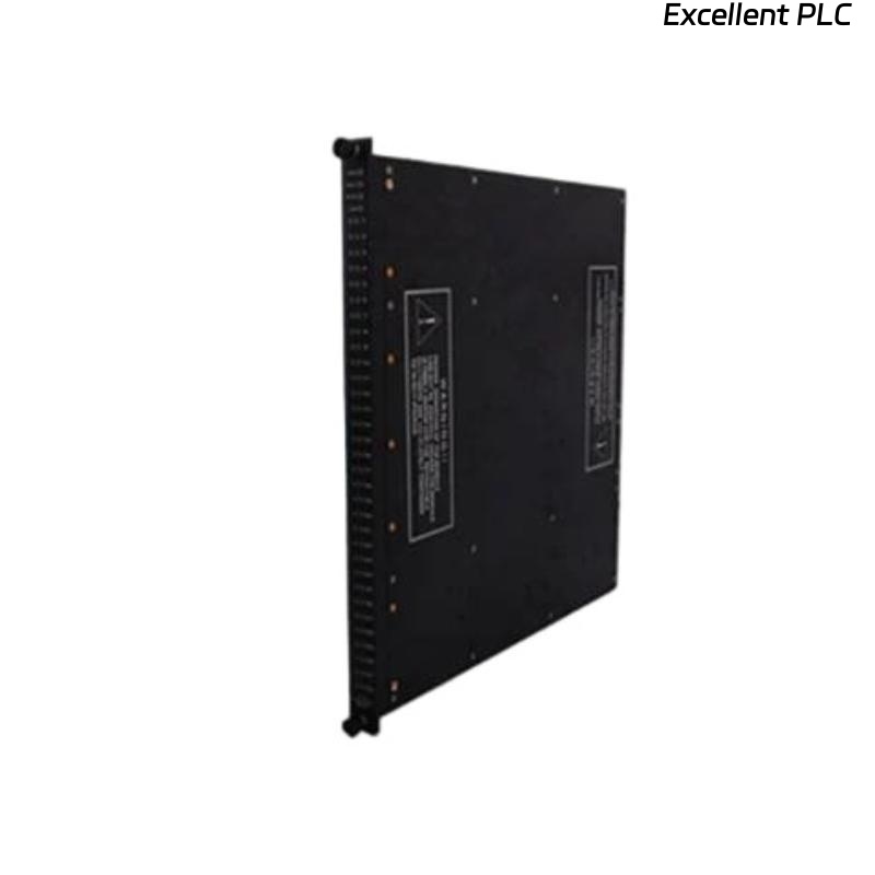
The Triconex 3000142-220 is a power module responsible for supplying stable voltages to CPUs, I/O modules, and interface units in TMR (Triple Modular Redundant) systems. When it fails to provide power or shows physical damage, careful troubleshooting and repair are required to avoid further system issues.
Initial Safety Precautions
Before touching the module, ensure that all rack power is completely off and that LOTO (lockout/tagout) procedures are in place. Wear an anti-static wrist strap and work on an ESD-safe mat. One field technician emphasizes:
“If you rush this step, even a small spark can take out the CPU along with the power module.”
Assess the Damage
Remove the module carefully and inspect it visually. Look for:
-
Burnt traces or components
-
Cracked or deformed PCB areas
-
Melted or broken connectors
If the damage is severe—such as burnt power regulators or physically cracked PCBs—replacement is often safer than repair.
Field note: Minor surface burns or connector damage can sometimes be repaired; catastrophic board damage usually warrants a spare module.
Check Input and Output Voltages
If the module is physically intact but not supplying power:
-
Measure the input voltage from the rack; it must be stable and within specification.
-
Check the main output rails (commonly 5 V, 24 V DC) for presence and ripple.
Often, intermittent or zero output is caused by blown fuses, burnt diodes, or failed regulators.
Component-Level Repair
For modules with minor damage:
-
Replace blown fuses or burnt diodes.
-
Inspect electrolytic capacitors for leakage or swelling; replace if necessary.
-
Measure key voltages at onboard regulators; replace failing ICs with equivalent parts.
Engineer tip: Only attempt component-level repair if you have experience with high-reliability TMR electronics. Otherwise, replacement is safer.
Cleaning and Connector Check
-
Clean oxidized or dirty connectors using proper contact cleaner.
-
Inspect the edge connector or rack connector for bent pins.
-
Ensure that the module will fully seat and make good contact when reinstalled.
Post-Repair Testing
Once repairs are complete:
-
Bench-test the module in an isolated rack with a known-good load.
-
Verify that all output voltages are within specification.
-
Observe for overheating or instability during a short burn-in test.
Pro tip: Never reinstall a repaired module into production without thorough bench testing.
Final Recommendations
-
Document all repairs and measurements for maintenance records.
-
Keep a spare 3000142-220 power module in stock; power module failures are common and critical.
-
If the module shows signs of severe PCB or component damage, do not risk running it in the system—replacement is the safer route.
Summary from field engineers: “A damaged power module is a system risk. Minor repairs are possible, but never skip testing—your CPUs depend on it.”