

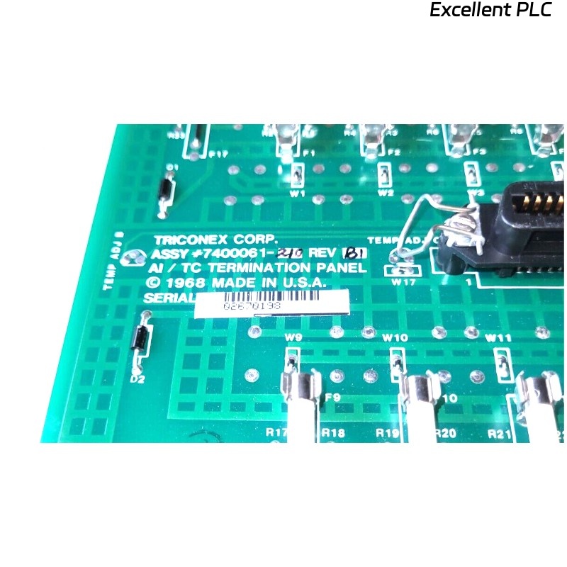
The Triconex 2750-2 (part number 7400061-210) is a terminal panel used to interface field devices with the TMR (Triple Modular Redundant) control system. Proper replacement ensures system safety and reliability.
1. Safety First – Power Down Everything
-
Switch off the power to the FSC or TMR rack.
-
Confirm the main power is off and lock out/tag out (LOTO) is applied.
-
Use an anti-static wrist strap and mat to protect the terminal panel electronics.
Field advice: “Never rush this step—power on while removing the panel can fry components.”
2. Prepare for Removal
-
Clear the work area around the panel.
-
Remove any obstructions, including covers or wiring ducts.
-
Review wiring diagrams and take a photo of existing cable connections for reference.
Experienced engineers recommend labeling every wire before disconnecting.
3. Disconnect Field Wiring
-
De-energize all connected field devices.
-
Loosen terminal screws and carefully disconnect wires.
-
Keep wires organized and labeled according to the previous diagram.
Tip: Use small cable ties or color-coded labels to prevent mistakes during reconnection.
4. Remove the Old Panel
-
Unscrew or unlatch the panel from the rack or mounting bracket.
-
Gently pull the panel out to avoid damaging connectors on the backplane.
-
Inspect the backplane for dust, debris, or oxidation while the panel is removed.
Veteran engineers say: “A clean backplane makes the new panel slide in smoothly.”
5. Install the New Terminal Panel
-
Align the new 7400061-210 panel with the rack or bracket.
-
Carefully engage the backplane connector without forcing it.
-
Secure the panel using screws or latches, ensuring it is firmly in place.
Pro tip: Slight misalignment can prevent the panel from making proper contact—always double-check before tightening screws.
6. Reconnect Field Wiring
-
Connect each wire according to the photo and labels made before removal.
-
Verify polarity, shielding, and grounding.
-
Tighten terminal screws to the recommended torque (usually 0.5–0.6 Nm).
Field note: Loose or reversed connections are the most common cause of post-replacement faults.
7. Power-Up and Initial Check
-
Restore power to the rack.
-
Observe status LEDs on the panel for OK or Error indications.
-
If any LED indicates a fault, double-check wiring and panel seating.
Engineer experience: The panel should “wake up” immediately; if it doesn’t, recheck backplane connection first.
8. Functional Verification
-
Activate connected field devices and confirm the panel reports correct signals.
-
Use Triconex diagnostics to ensure communication is stable and redundancy paths function correctly.
-
Document test results for maintenance records.
Tip from field service engineers: Run a short burn-in test for a few hours before full system integration.
9. Post-Installation Recommendations
-
Keep the removed panel for inspection or as a spare if still functional.
-
Periodically inspect the new panel and connectors to prevent long-term issues.
-
Always update wiring and maintenance documentation after replacement.
Remember: Careful labeling, clean installation, and thorough testing prevent repeat faults.