

📘 1. Introduction
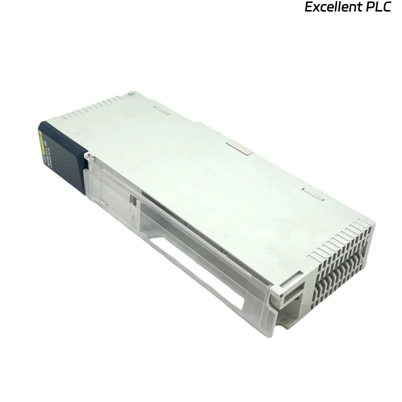
The Schneider 140EDK21100 is a communication processor module for Modicon Quantum PLC systems.
It enables fast and reliable data exchange between the PLC and external devices, including HMIs, SCADA systems, and other Ethernet-enabled controllers.
This guide provides a step-by-step installation procedure, practical tips, and troubleshooting recommendations to ensure smooth field deployment.
⚙️ 2. Required Tools & Preparation
Before installation, ensure the following tools and materials are available:
-
ESD wrist strap
-
Flat-head screwdriver (2–3 mm)
-
Shielded CAT5e/CAT6 Ethernet cable
-
Laptop with EcoStruxure Control Expert or Concept
-
Multimeter for voltage verification
⚠️ Safety Note: Always power down the PLC rack before inserting or removing modules to avoid backplane damage.
🏗️ 3. Hardware Overview
| Parameter | Details |
|---|---|
| Model | Schneider 140EDK21100 |
| Function | Communication Processor Module |
| Interface | Ethernet TCP/IP, Modbus TCP, Global Data |
| Port | 1 × RJ-45 (10/100 Mbps) |
| Indicators | RUN, ERR, LINK, ACT LEDs |
| Power Supply | 5 VDC via Quantum backplane |
| Mounting | Rack slot in Quantum PLC |
| Operating Temperature | 0–60°C |
🧠 Engineer Tip: Ensure the module version matches your project configuration to avoid ERR LED during startup.
🔧 4. Installation Steps
Step 1 — Power Down
-
Turn off the main power to the PLC rack.
-
Disconnect all field devices connected to the target slot.
Step 2 — Physical Installation
-
Identify the designated slot on the Quantum rack.
-
Align the 140EDK21100 module with the guide rails.
-
Slide it evenly into the backplane until it clicks securely.
-
Fasten the module with the side latch or screw.
⚠️ Avoid applying lateral force — uneven insertion may damage the backplane contacts.
Step 3 — Ethernet Connection
-
Connect a shielded CAT5e/CAT6 cable from the module RJ-45 port to your industrial switch or network hub.
-
Ensure proper grounding to reduce electromagnetic interference.
-
If using a network with multiple PLCs, verify unique IP addresses and subnet configurations.
🖥️ 5. Software Configuration
-
Launch EcoStruxure Control Expert.
-
Add the 140EDK21100 module in the correct slot within the rack configuration.
-
Configure Ethernet parameters:
-
Static IP or DHCP
-
Subnet mask
-
Gateway (if required)
-
-
Enable communication protocol (e.g., Modbus TCP, Global Data).
-
Download the configuration to the PLC.
-
Test communication by pinging the module from your engineering workstation.
💡 Pro Tip: Always assign static IP addresses in production networks to prevent conflicts.
🔍 6. LED Indicators Reference
| LED | Color | Status | Meaning |
|---|---|---|---|
| RUN | Green | ON | Module initialized and operational |
| ERR | Red | OFF | Normal |
| ERR | Red | ON | Configuration or hardware fault |
| LINK | Green | ON | Ethernet link detected |
| ACT | Yellow | Flashing | Active data transmission |
🔧 7. On-Site Verification
-
Confirm RUN LED is solid green after power-up.
-
Ping the module from your PC to verify network connectivity.
-
Use Control Expert to check for correct Global Data or Modbus TCP communication.
-
Observe LINK and ACT LEDs for normal network activity.
🧰 8. Troubleshooting Common Issues
| Symptom | Possible Cause | Recommended Action |
|---|---|---|
| ERR LED ON | Firmware mismatch | Update module firmware to match project |
| No LINK light | Bad Ethernet cable or switch port | Check cable, swap ports |
| Cannot ping module | IP conflict or firewall | Assign unique IP, disable firewall temporarily |
| Intermittent communication | EMI interference | Use shielded cables, separate from high-voltage lines |
| PLC project does not recognize module | Incorrect slot configuration | Re-add module in software |
🧾 9. Maintenance Tips
-
Inspect Ethernet connections and cabling periodically.
-
Keep firmware up-to-date via Schneider support portal.
-
Label cables and ports to simplify future maintenance.
-
Avoid running multiple firmware updates simultaneously on networked modules.
🧠 Field Note: Communication processor reliability is usually determined by proper cabling and configuration, not by the module itself.
✅ 10. Final Verification Checklist
-
[✔] Module securely mounted in rack
-
[✔] Ethernet cable properly connected and grounded
-
[✔] RUN LED green, ERR LED off
-
[✔] Module reachable via ping
-
[✔] Modbus TCP / Global Data verified in Control Expert
After these checks, the 140EDK21100 module is fully operational and integrated into the Quantum PLC system.