

📘 1. Introduction
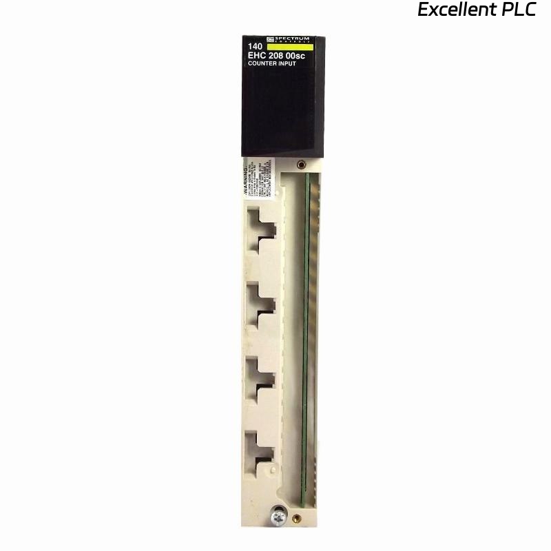
The Schneider 140EHC20800 is an analog counter module for Modicon Quantum and Momentum PLC systems.
It allows precise counting of analog input pulses and converts them into digital values for process control, measurement, and monitoring applications.
This guide provides a step-by-step on-site installation procedure, practical tips, and troubleshooting advice to ensure reliable operation in industrial environments.
⚙️ 2. Tools & Preparation
Before installation, make sure you have:
-
Anti-static wrist strap
-
Small flat-head screwdriver
-
Torque wrench for terminal screws
-
Shielded analog input cabling
-
Multimeter (for verifying signal levels)
-
Laptop with EcoStruxure Control Expert or Concept software
⚠️ Safety Reminder: Always disconnect power from the PLC rack before module installation or wiring.
🏗️ 3. Hardware Overview
| Parameter | Details |
|---|---|
| Model | Schneider 140EHC20800 |
| Function | Analog input pulse counter |
| Channels | 8 analog counting channels |
| Input Range | 0–10 V / 4–20 mA configurable |
| Power Supply | 5 VDC via Quantum/Momentum backplane |
| Indicators | RUN, ERR LEDs |
| Mounting | PLC rack slot |
| Operating Temp | 0°C – 55°C |
🧠 Engineer Tip: Ensure that the backplane slot chosen provides stable 5V supply for accurate counting.
🔧 4. Installation Steps
Step 1 — Power Down the Rack
-
Disconnect all field devices and ensure PLC power is off.
-
Wait 10–15 seconds for residual voltage to discharge.
Step 2 — Module Mounting
-
Identify the designated rack slot.
-
Align the 140EHC20800 module with the guide rails of the backplane.
-
Slide it into the slot until it clicks securely.
-
Lock the module using side screws or clip.
⚠️ Avoid forcing the module — misaligned pins can damage the backplane bus.
Step 3 — Analog Signal Wiring
-
Connect each analog signal source to the corresponding channel input.
-
Use shielded cables to minimize electrical noise.
-
For current inputs (4–20 mA), connect a precision resistor if required per the installation manual.
-
For voltage inputs (0–10 V), ensure proper range and polarity.
🧩 Pro Tip: Keep analog cabling separated from high-power motor cables to avoid interference.
🖥️ 5. Software Configuration
-
Open EcoStruxure Control Expert.
-
In the project, select the slot where 140EHC20800 is installed.
-
Add the module in the hardware configuration.
-
Set channel parameters:
-
Input type (Voltage or Current)
-
Signal filtering (low-pass)
-
Scaling factor (counts per unit)
-
-
Download configuration to the PLC.
-
Monitor live input values to verify proper counting.
💡 Engineer Insight: Always test each channel with a known reference signal before full-scale operation.
🔍 6. LED Indicator Reference
| LED | Color | Status | Meaning |
|---|---|---|---|
| RUN | Green | ON | Module initialized |
| ERR | Red | OFF | Normal operation |
| ERR | Red | ON | Hardware or configuration fault |
If ERR LED remains on after download, check:
-
Channel wiring and signal type
-
Module firmware compatibility
-
Backplane 5V supply stability
🔧 7. On-Site Verification
-
Apply a test signal to each channel.
-
Verify count value accuracy in software.
-
Monitor RUN/ERR LEDs during operation.
-
Record initial readings for future troubleshooting reference.
🧰 8. Troubleshooting Common Issues
| Symptom | Possible Cause | Recommended Action |
|---|---|---|
| ERR LED ON | Misconfigured input type | Check voltage/current settings |
| No counts recorded | Loose wiring or broken signal | Verify cable and signal source |
| Interference or noisy readings | High EMI | Use shielded cables and proper grounding |
| Wrong scaling | Incorrect software scaling factor | Adjust scaling in EcoStruxure software |
| Module not recognized | Firmware mismatch | Update to latest compatible firmware |
🧾 9. Maintenance Tips
-
Inspect cables and terminals periodically for wear.
-
Keep module ventilation clear to avoid overheating.
-
Backup module configuration after each system update.
-
Calibrate input signals annually if the process requires high accuracy.
💡 Field Tip: Analog counters are extremely reliable — most failures come from wiring, configuration, or signal issues, not the module itself.
✅ 10. Final Verification Checklist
-
[✔] Module seated securely in rack
-
[✔] All analog channels wired correctly
-
[✔] Configuration downloaded to PLC
-
[✔] RUN LED active, ERR LED off
-
[✔] Test signals accurately recorded in software
-
[✔] Shielding and grounding verified
Once all checks pass, the Schneider 140EHC20800 module is ready for reliable operation in your PLC system.