

📘 1. Introduction
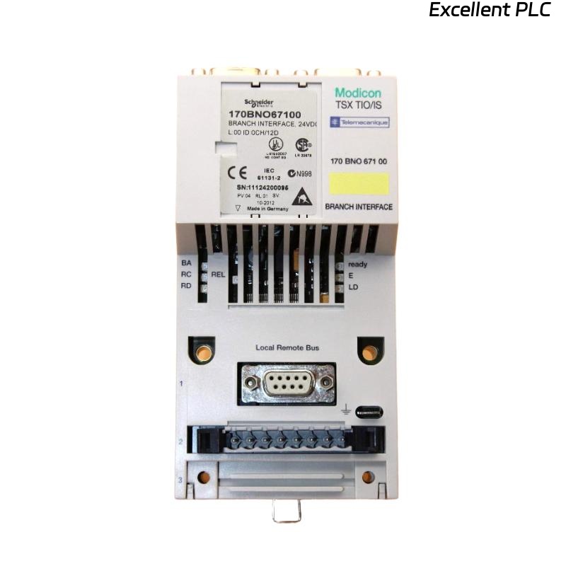
The Schneider 170BNO67100 is a Momentum I/O Bus Network Adapter, designed to interface distributed I/O bases within the Modicon Momentum PLC system.
Its main role is to extend the local I/O bus, enabling modular system expansion and reliable communication between CPU adapters and remote I/O units.
Unlike standard communication modules, the 170BNO67100 handles I/O bus timing, signal buffering, and synchronization, making correct installation critical for system stability.
🧰 2. Tools & Materials Required
Before beginning the installation, prepare the following:
-
Anti-static wrist strap (for ESD protection)
-
Flat-head screwdriver (2.5 mm)
-
DIN rail mounting clips (if applicable)
-
Shielded twisted-pair communication cable
-
Verified power supply (24 VDC, regulated)
-
Multimeter or cable tester
⚠️ Safety Reminder: Always disconnect PLC power before inserting or removing Momentum modules.
🧩 3. Physical Overview
| Parameter | Description |
|---|---|
| Model | Schneider 170BNO67100 |
| Type | I/O Bus Network Adapter |
| Mounting | Momentum I/O base slot (right side) |
| Power | Supplied through I/O base |
| Interface | Momentum I/O bus and remote extension connector |
| Operating Temperature | 0°C – 60°C |
💡 The module is plug-in type and must align precisely with the Momentum I/O base and adjacent modules.
🧱 4. Installation Steps
Step 1: Prepare the System
-
Power off the entire Momentum PLC rack.
-
Verify that all I/O modules and CPU adapters are properly labeled and documented.
-
Ensure environmental conditions meet the recommended humidity and temperature levels.
Step 2: Mount the Module
-
Locate the rightmost slot on the Momentum base or the intended expansion rack.
-
Align the 170BNO67100 module with the guide rails.
-
Press firmly until you hear a “click,” indicating full engagement with the bus connector.
-
Secure the module using side clips or screws if required.
✅ Tip: The bus connector must be fully seated; even a slight misalignment can prevent data exchange.
Step 3: Connect the Network Cable
The 170BNO67100 uses a dedicated I/O bus extension cable to link with another Momentum I/O rack.
| Connector | Function | Cable Type |
|---|---|---|
| BUS OUT | Output to next I/O rack | Shielded twisted-pair |
| BUS IN | Input from previous rack | Shielded twisted-pair |
Wiring recommendations:
-
Cable length: max 3 meters between racks.
-
Use 120-ohm terminating resistor at the last rack.
-
Ground the shield at one end only (preferably at the control cabinet side).
🧩 Keep I/O bus cables separated from high-voltage or motor power lines to prevent EMI.
Step 4: Power and Communication Check
-
Reapply power to the Momentum system.
-
Observe LEDs on the 170BNO67100 module:
| LED | Status | Meaning |
|---|---|---|
| PWR (Green) | ON | Power supply OK |
| BUS (Green) | Blinking | Active communication |
| ERR (Red) | Off | Normal operation |
| ERR (Red) | ON | Bus fault or termination error |
-
If ERR LED is on:
-
Check bus cable continuity and termination.
-
Verify the BUS IN/OUT orientation is correct.
-
Confirm that all connected racks are powered and correctly addressed.
-
🔧 5. Configuration in Software
After physical installation, you need to configure the module in Schneider’s Concept, ProWORX, or EcoStruxure Control Expert software.
Configuration Steps:
-
Open your PLC project.
-
Navigate to the I/O configuration tree.
-
Add a 170BNO67100 module in the correct rack position.
-
Define the communication link between the main CPU and the remote rack.
-
Download the configuration to the controller.
✅ Verification: In the diagnostics window, check that all I/O points on the extended rack are online and responding.
🧮 6. Typical Installation Layout
The 170BNO67100 essentially serves as a bridge between Momentum racks, ensuring that remote I/O behaves as if it were local.
🧠 7. Common Installation Mistakes & Fixes
| Mistake | Symptom | Solution |
|---|---|---|
| BUS IN/OUT reversed | ERR LED ON | Swap connectors |
| Missing terminator | Unstable I/O readings | Add 120 Ω resistor at the end |
| Shared cable ground | Communication noise | Ground only at one end |
| Loose module connection | No communication | Reseat module |
| Using non-shielded cable | Random I/O loss | Replace with shielded pair |
🧾 8. Preventive Maintenance
| Task | Interval | Description |
|---|---|---|
| Visual inspection | Every 6 months | Check connectors for oxidation |
| Cable continuity test | Yearly | Verify bus cable resistance <1 Ω |
| Firmware check | Annually | Update to latest version for stability |
| Environmental audit | Each shutdown | Ensure temperature & humidity within limits |
✅ 9. Final Verification Checklist
Before closing the control cabinet, ensure:
-
[✔] All modules are securely mounted and aligned.
-
[✔] Termination resistors installed at end-of-line rack.
-
[✔] No LED errors remain on any connected module.
-
[✔] PLC recognizes all remote I/O channels.
Once verified, the Schneider 170BNO67100 is ready for full operation.
🏁 10. Engineer’s Note
The 170BNO67100 may look like a simple bus adapter, but it’s the backbone of distributed Momentum systems.
A single installation error — reversed cable, missing terminator, or poor grounding — can cause days of intermittent communication problems.
💬 “In industrial networking, stability isn’t achieved by software — it’s achieved by good wiring.”