

Hey everyone, Tech Talk with Mark here. Today, we’re diving deep into a classic and frustrating problem that can stop any rotating machinery engineer in their tracks: your Bently Nevada 3300 monitoring system suddenly shows a vibration or displacement signal that’s dropped straight to zero. That steady, reliable waveform on your monitor is gone, replaced by a flat line and likely a scary “BAD” or “BYPASS” alarm.
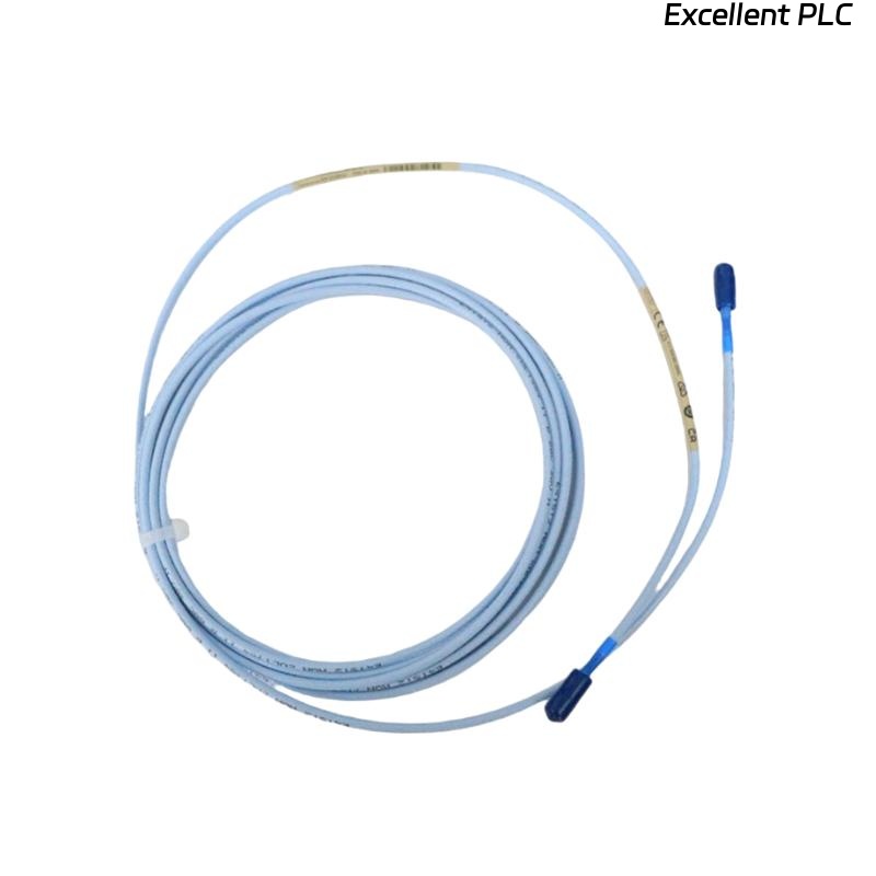
If you’re working with a ceramic-capped proximity probe like the 164517-050-10-01-RU, don’t panic. This isn’t necessarily a catastrophic machine failure. More often than not, it’s an electrical fault in the sensor loop. Let’s walk through exactly how to diagnose and fix this, step-by-step.
Understanding the “Why”: The Shorted Signal Loop
First, a quick primer. The 3300 system works by the proximitor powering the probe with a high-frequency signal. The distance to the metal target (your shaft) changes the impedance of the probe’s coil, which the proximitor converts into our beloved DC gap voltage (-10 VDC typical) and AC vibration signal.
A zero signal means the system sees an impedance so low it’s essentially a short circuit. The proximitor can’t develop any voltage, so it outputs zero. For our durable ceramic-capped probes, the issue is almost never a worn-out tip, but what’s on it or connected to it.
Step-by-Step Diagnosis: Finding the Short
⚠️ Safety First: Before touching anything, coordinate with operations. If you’re checking connections on a running machine (which we sometimes must do), be extremely aware of rotating parts and hot surfaces.
Step 1: The 60-Second Visual & Connection Check
Start simple. This solves about 40% of cases.
-
The Connector: Is the threaded connection between the probe body and the extension cable tight? Vibration can loosen it. Give it a firm hand-tight check. A loose connection can allow the shield to shift and short.
-
The Cable Path: Do a quick scan along the cable’s run. Is it pinched, cut, or soaked in oil? Look for obvious damage.
Step 2: The “Smoking Gun” Test – Gap Voltage Check
This is your most powerful diagnostic tool. On your 3500 monitor or via your DCS, look up the DV (Gap Voltage) parameter for the faulty channel.
-
The Reading: If your signal is 0, you’ll likely see a gap voltage very close to 0 VDC (e.g., -0.5 to +0.5 VDC).
-
The Diagnosis: This confirms a short circuit in the loop. The proximitor is alive, but its output is being pulled to ground.
Step 3: Isolate the Short – Disconnect and Measure
Now we play detective. You’ll need a good digital multimeter.
-
At the Proximitor: Power down the system if possible (removing the -24VDC). Disconnect the extension cable from the proximitor input (likely a BNC or screw terminal).
-
Resistance Check: Set your multimeter to measure resistance (Ohms). Measure between the center conductor (signal) and the outer shell/sleeve (ground) of the disconnected cable.
-
A Healthy Cable & Probe will show a relatively high resistance (> 1 kΩ and likely much higher).
-
The Faulty System will show a very low resistance—we’re talking a few Ohms or even zero. Bingo, you’ve found the short.
-
Step 4: Find the Exact Location
The short could be in the extension cable or at the probe itself.
-
Go to the Probe Junction: Find where the probe and extension cable connect (usually at the machine case). Disconnect them.
-
Test the Probe Alone: Measure resistance between the two pins of the probe side of the connector. A good 8mm probe should read 7.5-9.5 Ω. If it reads very low (< 1Ω), the internal coil is shorted (rare, but possible).
-
Test the Extension Cable Alone: Measure from the connector end to the end you disconnected at the proximitor, again between center pin and outer sleeve. It should read open circuit (OL). If it reads short, your cable is damaged.
Most Common Culprits:
-
Shield Contact at the Proximitor: The braided shield inside the cable connector at the proximitor end has frayed and is touching the center pin. This is #1 on the hit list.
-
Conductive Contamination on the Ceramic Cap: While the ceramic is an excellent insulator, a thick, wet buildup of conductive oil sludge or metal dust can create a path from the probe’s sensitive tip to its metal body (ground). Carefully clean the cap with isopropyl alcohol and a lint-free cloth.
-
Damaged/Pinched Cable: The cable’s insulation has been breached, shorting the center conductor to the shield.
The Repair and Prevention Playbook
Repair:
-
For Shield Contact: Carefully trim back any frayed shield wires in the connector. Ensure only the center conductor contacts its terminal, and the shield is properly captured in its insulated backshell. Crucially, verify your system uses a SINGLE-POINT GROUND. The cable shield should only be grounded at the rack/panel, not at the probe end.
-
For Contamination: Clean the probe tip. Consider if the environment needs a protective boot or if purge air is required.
-
For Cable Damage: Replace the extension cable. Use the correct OEM or high-quality equivalent part.
Prevention:
-
Torque Those Connectors: During installation, use a spanner. Hand-tight plus a 1/8th turn is the rule. Don’t over-tighten.
-
Secure Cable Routing: Use clamps and conduits. Keep sensor cables at least 1 meter away from power cables and VFDs.
-
Regular Inspection: Make a quick “connector check” part of your monthly rounds.
Bottom Line
A zero signal on your Bently 3300 probe is a symptom of a short. It’s rarely the machine, and it’s almost never the monitor. The fault lies in the sensor loop—start at the gap voltage, then systematically isolate sections until your multimeter finds the low resistance path. Fixing it is often a 15-minute job of re-terminating a connector or cleaning a probe tip.
Stay safe, and keep those signals clean!
Got a different symptom, like a pegged max signal or erratic noise? Let me know in the comments—we’ll tackle that next time.