

Hey everyone, Mark here from the field. Today we’re tackling a classic alarm that’ll get any reliability engineer’s attention: your vibration or displacement channel is pinned at its maximum reading. The waveform is gone, replaced by a flat line stuck at the top of the scale, accompanied by a “Sensor Fault” or “Overrange” alarm on your 3500 monitor.
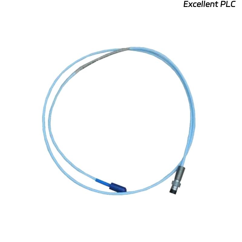
If you’re working with a Bently Nevada 3300 system and a ceramic-capped probe like the 164517-050-10-01-RU, don’t assume the worst about your machinery just yet. This “pegged” signal is almost always a hard failure in the sensor circuit itself—specifically, an open circuit. Let’s break down exactly how to diagnose and fix this, step by step.
The Root Cause: Understanding the Open Circuit Failure
First, a quick system refresher. The proximitor sends a radio frequency signal to the probe coil. The distance to the target (your shaft) changes the coil’s impedance, which the proximitor converts to our standard DC gap voltage (typically -10 VDC) and AC vibration signal.
An open circuit means the electrical loop is broken. The proximitor cannot “see” the probe coil at all. In this fault state, the proximitor’s output circuitry drives to its negative saturation voltage, typically between -22 VDC and -24 VDC. To the monitor, this far exceeds the normal operating range (-2 to -18 VDC) and is interpreted as a maximum negative signal, displayed as a pegged or overrange condition.
The Diagnostic Process: A Systematic Approach
⚠️ Safety First: Always follow your site’s safety and lock-out/tag-out procedures. If troubleshooting on a running machine is necessary, maintain extreme awareness of rotating equipment and hot surfaces.
Step 1: The 5-Minute Physical & Connection Check
Start with the simple, high-probability fixes. This solves a surprising number of cases.
-
The Connector Check (Most Likely Culprit): Go directly to the threaded connections. Check both ends: where the probe meets the extension cable at the machine case, and where the extension cable plugs into the proximitor. Are they finger-tight plus a proper wrench turn? Vibration is the enemy of loose connectors.
-
The Cable Run Visual Scan: Quickly trace the path of the extension cable. Look for obvious damage: crushing, cuts, or abrasion. Check if it’s been exposed to excessive heat or chemical spray.
Step 2: The Key Evidence – Check the Gap Voltage (DV)
This is your most critical diagnostic data point. On your 3500 monitor or through the DCS, call up the DV (Gap Voltage) parameter for the faulted channel.
-
The Telling Reading: With a pegged signal, you will almost certainly see a gap voltage reading very close to -22 VDC to -24 VDC.
-
The Conclusion: This confirms an open circuit in the sensor loop. The proximitor is powered but is operating in its fault saturation mode.
Step 3: Isolation & Measurement – Finding the Break
Now, grab your digital multimeter. Our goal is to isolate whether the break is in the probe, the cable, or at a connector.
-
Start at the Proximitor (Safely): If possible, de-energize the system by removing the -24VDC power. Disconnect the extension cable from the proximitor input.
-
Measure Loop Resistance: Set your multimeter to Ohms (Ω). Measure across the two pins/conductors of the disconnected cable.
-
A Healthy Loop will show a resistance between 8 Ω and 12 Ω (the coil resistance plus a small amount of cable resistance).
-
A Faulty Loop will show “OL” (Over Limit) or a very high resistance (MΩ). This confirms the open circuit.
-
Step 4: Pinpointing the Exact Failure Point
Where is the break? We need to split the system.
-
Locate the Field Junction: Find the connection point between the probe and the extension cable (usually a junction box on the machine). Disconnect them.
-
Test the Probe Alone: Measure the resistance across the two pins of the probe side. A standard 8mm probe like the 164517-050-10-01-RU should read 7.5 – 9.5 Ω.
-
If it reads “OL”, the internal coil has failed. This is less common but possible due to extreme thermal cycling or mechanical fatigue.
-
-
Test the Extension Cable Alone: Measure continuity through the cable from one end to the other. It should be nearly 0 Ω. If it reads “OL”, the cable has an internal break.
Most Common Faults, Ranked:
-
Loose Connection: The #1 offender. The threaded connector has vibrated loose, breaking electrical contact.
-
Damaged/Cut Cable: The cable has been pinched, crushed, or severed, breaking the internal wire.
-
Failed Probe Coil: The fine wire inside the probe has fractured.
The Repair & Prevention Protocol
Repair Actions:
-
For Loose Connections: Tighten the connector firmly. The standard practice is hand-tight, then use a spanner for an additional 1/8th turn. Do not over-torque.
-
For a Damaged Cable: Replace the extension cable. Use an OEM or high-quality equivalent with proper shielding.
-
For a Failed Probe: Replace the probe. Ensure the replacement (e.g., 164517-050-10-01-RU) has the same sensitivity (e.g., 7.87 mV/µm). Critical: After replacing any component, you must re-gap the probe to achieve -10 VDC and verify the system calibration.
Prevention Best Practices:
-
Scheduled Connection Checks: Add “check and secure vibration probe connectors” to your quarterly or semi-annual preventive maintenance routines.
-
Proper Cable Management: Secure cables with clamps and route them in dedicated trays or conduits away from foot traffic and moving parts.
-
Strategic Sparing: Keep a critical spare, such as an extension cable, in stock for quick replacement and to aid in fault isolation.
The Bottom Line for the Field Engineer
A pegged maximum signal on your Bently 3300 system is a clear call to action: find the open circuit. The diagnostic path is straightforward: verify the saturated gap voltage -> isolate sections and measure resistance. Start with the simple stuff—tighten those connectors—before moving to component replacement.
A reliable signal depends on a continuous electrical path. Keep yours intact.
Dealing with noisy, erratic data instead of a clean failure? Let me know in the comments if you want the next deep-dive on troubleshooting unstable signals and EMI problems.