

By Rachel Kim – Senior Control Systems Engineer
Industrial fans often sit near motors, transformers, or large switchgear. While the fan itself may spin without incident, the monitoring electronics can be surprisingly sensitive to electromagnetic interference (EMI).
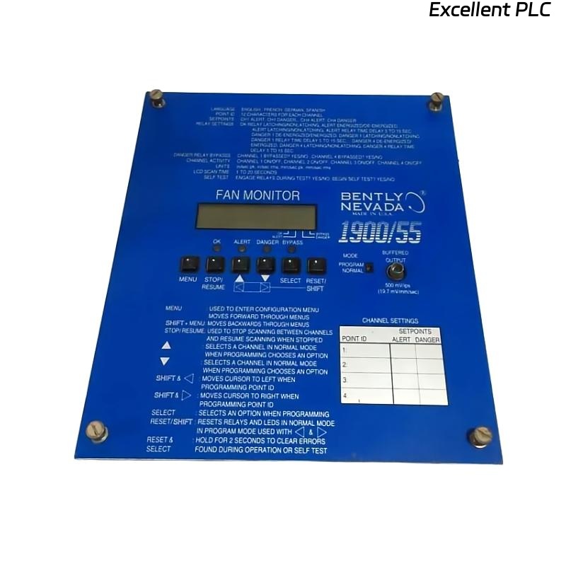
We recently faced a case where a Bently Nevada 1900/55-01-02-01-01 fan monitor repeatedly reported RPM drop alarms during high-load operations, while the fan continued spinning normally. The intermittent alarms disrupted both control logic and automated reporting, triggering unnecessary maintenance actions.
Step 1: Symptom Analysis
Operators reported:
-
Fan RPM drops during load changes, lasting 1–3 seconds
-
Historical data showed spikes in the monitoring signal coinciding with nearby high-power switching events
-
No mechanical anomalies detected
Initial inspection ruled out wiring breaks, sensor misalignment, or grounding issues. The fault pattern suggested electromagnetic coupling, which is subtle and intermittent.
Step 2: Data Logging and Signal Inspection
We configured the fan monitor in the DCS to log raw input values:
Plotting the raw data revealed high-frequency spikes superimposed on the true fan RPM. These spikes were sufficient to trigger the fan module’s alarm logic.
Step 3: EMI Source Identification
-
High-current motor contactors located within 2 meters of the fan monitor cabling
-
Switching events synchronized with alarm occurrences
-
Shielded twisted-pair cables partially grounded, but proximity to AC lines induced noise
Conclusion: EMI from motor switching coupled into the monitor signal line, causing transient errors.
Step 4: Corrective Measures
Electrical mitigation:
-
Re-route fan monitor signal cables away from high-current AC lines.
-
Fully ground both ends of shielded twisted-pair cables.
-
Install ferrite chokes at both ends of the fan monitor signal cable to suppress high-frequency noise.
DCS/PLC logic filtering (pseudo-implementation example):
This logic effectively ignores transient RPM spikes caused by EMI while still responding to genuine fan stoppages.
Step 5: Verification
After the mitigation:
-
Observed fan RPM for multiple load cycles
-
Confirmed no false alarms during motor switching
-
Captured clean signal traces with high-resolution logging
The fan monitor returned to stable operation, providing reliable RPM data.
Key Learnings
-
High-power electrical equipment near sensors is a constant EMI source. Even shielded cables are vulnerable if grounding is inconsistent.
-
Raw data logging is invaluable. Without inspecting the underlying signal, the root cause would have been misdiagnosed as a fan or sensor fault.
-
DCS/PLC filtering complements hardware fixes. Software logic can mitigate transient events without masking real faults.
-
Preventive cable management: always route sensor cabling away from high-current AC paths and apply ferrites or filters proactively.
Conclusion
The Bently Nevada 1900/55-01-02-01-01 fan monitor is extremely reliable when supplied with clean signals and properly shielded cabling. But in industrial environments, EMI is a silent adversary. Combining hardware shielding, proper grounding, and smart software filtering ensures continuous, accurate monitoring without false alarms.
Even the best monitors can be fooled by their environment—but with careful design and attention to detail, you can keep them honest.
— Rachel Kim