

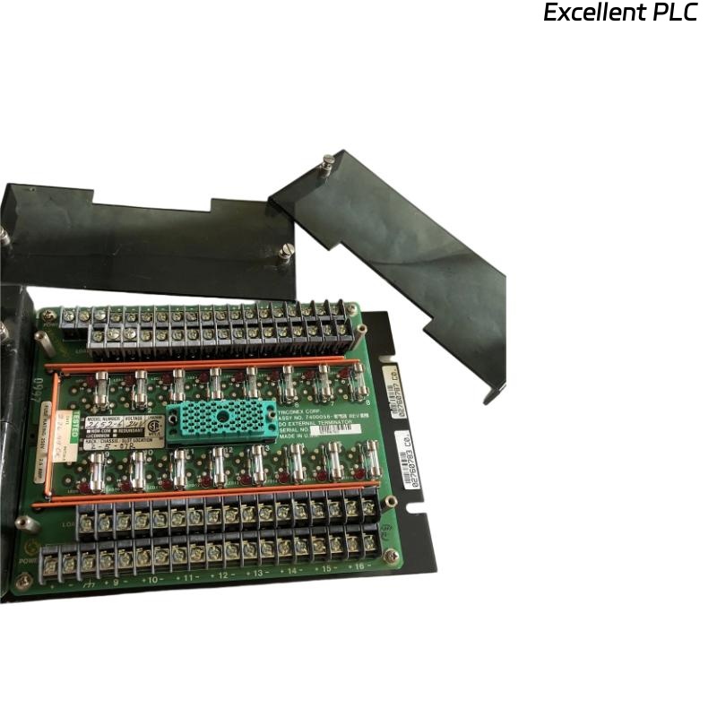
❓ What Is the 3000120-380 DI External Terminator?
The Triconex 3000120-380 DI External Terminator is used to provide electrical termination, signal conditioning, and isolation for digital input (DI) channels in a Tricon TMR (Triple Modular Redundant) safety control system.
It ensures that all input signals are accurately received by the system’s logic solver without electrical noise or cross-channel interference.
⚙️ Q1: What Are the Technical Specifications?
| Parameter | Description |
|---|---|
| Model | Triconex 3000120-380 |
| Function | Digital Input (DI) External Terminator |
| Compatible Modules | Tricon DI series modules |
| Input Voltage | 24 VDC nominal |
| Mounting | DIN-rail or panel mounted |
| Connection | Screw-type terminal block |
| Operating Temp | 0°C – 60°C |
| Purpose | Termination and filtering of field digital signals |
🧰 Q2: What Tools and Materials Are Required?
-
ESD wrist strap or anti-static mat
-
Flathead screwdriver (2.5 mm tip)
-
Wire ferrules and crimping tool
-
Multimeter for voltage verification
-
Shielded twisted-pair cables (recommended for long runs)
🧩 Q3: How to Install the Triconex 3000120-380 Terminator?
Step 1 — Safety and Power Off
Always switch off the Tricon system rack before wiring. Never connect or disconnect the terminator with power applied.
Step 2 — Identify the Installation Location
Mount the terminator next to the target DI module rack. Ensure the module’s channel numbering corresponds with terminal markings on the 3000120-380.
Step 3 — Wire the Field Signals
-
Strip 6–8 mm of insulation from each wire.
-
Connect signal wires to the respective channel input terminals.
-
Observe correct polarity for 24 VDC input signals.
-
Tighten screws securely to 0.5–0.6 N·m torque.
Step 4 — Connect Shield and Common
-
Connect shielded cable drain wires to the ground bus at the cabinet end.
-
Avoid grounding at both ends to prevent ground loops.
Step 5 — Visual Verification
-
Check all wire numbers match the documentation.
-
Ensure no strands or exposed copper remain outside terminals.
💡 Q4: What Should Be Checked After Installation?
Before applying power:
-
Perform a continuity test on each input.
-
Confirm no short circuits between adjacent terminals.
-
Verify all channel voltages are within the expected range (typically 24VDC ±10%).
After power-up:
-
Check that DI module LEDs show normal operation.
-
RUN: steady green
-
FLT: off
-
Channel LEDs: change according to field input status
-
⚠️ Q5: What Are the Common Installation Errors?
| Symptom | Likely Cause | Solution |
|---|---|---|
| Channel not responding | Loose wiring or reversed polarity | Recheck wiring and terminal torque |
| False ON/OFF transitions | EMI or improper shielding | Use shielded cable, ground at one end only |
| Fault LED active | Shorted input line | Inspect and replace damaged cable |
| Unstable readings | Poor grounding | Verify cabinet grounding system integrity |
🧮 Q6: What Are the Best Engineering Practices?
-
Use label markers on every wire and terminal for maintenance clarity.
-
Avoid routing signal cables parallel to power lines.
-
Keep cabinet humidity below 75% RH and temperature below 40°C.
-
Periodically re-tighten terminal screws during scheduled maintenance.
-
Record installation date and technician name for audit trail.
✅ Final Verification Checklist
Before closing the cabinet door, confirm:
☑ All input channels correctly wired and labeled
☑ Shielding connected on one end only
☑ Module LEDs in normal state
☑ No loose terminals or cable strain
📘 Summary
The Triconex 3000120-380 DI External Terminator provides precise and stable signal termination for digital inputs in safety-critical control systems.
Correct installation ensures signal integrity, minimizes noise, and guarantees long-term reliability of your Tricon TMR architecture.
In short: Stable wiring leads to stable safety logic.