

🏭 Background
During regular maintenance of a Triconex TMR safety control system, an operator reported intermittent signal loss and unstable input readings on a 3000604-100 Digital Input (DI) Module.
This module is essential for receiving field signals from critical process instruments, and its malfunction can trigger false shutdowns or safety logic errors if not properly diagnosed.
⚙️ Module Overview
| Specification | Description |
|---|---|
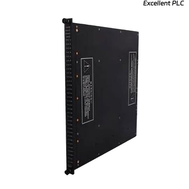
| Model | Triconex 3000604-100 |
| Type | Digital Input (DI) Module |
| Channels | 32 isolated inputs |
| Input Voltage | 24 VDC nominal |
| Function | Collects and conditions digital field signals |
| Redundancy | Triple Modular Redundant (TMR) design for fault tolerance |
⚠️ Reported Symptoms
-
Several channels remained constantly ON even when field devices were de-energized.
-
Input status LEDs on the front panel were flickering irregularly.
-
The system diagnostic utility showed “DI module communication error.”
-
After a warm restart, fault indication returned within 10 minutes.
🧠 Step 1 — Initial Verification
Before concluding that the DI module was defective, the maintenance team performed basic field checks:
-
Verified field wiring continuity — all circuits were intact.
-
Checked power supply stability — steady at 24.1 VDC.
-
Inspected backplane connectors — no visible oxidation or bent pins.
-
Swapped positions with a known good DI module — fault followed the module.
✅ Result: Confirmed that the problem originated within the 3000604-100 module itself.
🧩 Step 2 — Diagnostic Analysis
Upon removing the module, several observations were made:
-
Burnt odor and slight discoloration near the isolation IC area.
-
Internal PCB temperature (measured via thermal camera) reached 65°C, higher than normal (≤45°C).
-
Capacitor aging and microcracks observed on two input filter components.
Conclusion: Prolonged thermal stress and minor voltage spikes had gradually degraded input circuitry, leading to unstable signal thresholds.
🛠 Step 3 — Corrective Actions
| Action | Description |
|---|---|
| 1. Replace faulty capacitors and isolation ICs | Replaced aged input filter capacitors and re-soldered isolation IC (ISO124 series). |
| 2. Clean PCB and connector | Removed flux residue and dust using isopropyl alcohol. |
| 3. Update firmware | Loaded the latest Triconex module firmware version via the system configurator. |
| 4. Perform 24-hour thermal stress test | Ensured stable operation under 0–60°C temperature cycling. |
After repairs, the module was reinstalled and passed all self-diagnostic and redundancy verification tests.
🔍 Step 4 — Preventive Recommendations
To prevent similar failures in the future, the following maintenance strategies are advised:
-
Perform annual inspection of all DI modules for heat discoloration.
-
Maintain cabinet temperature under 40°C with continuous airflow.
-
Record module runtime hours and replace after 8–10 years of service.
-
Implement input surge protection on long field signal lines.
-
Keep spare DI modules in a dry, anti-static environment.
🧾 Engineering Insights
Field experience shows that Triconex DI modules rarely fail outright — degradation usually occurs due to thermal fatigue, power ripple, or environmental dust accumulation.
Regular preventive maintenance and firmware updates can extend the lifespan significantly.
As one senior field engineer summarized:
“A DI module doesn’t suddenly fail — it whispers through its LEDs before it screams.”
✅ Conclusion
The Triconex 3000604-100 Digital Input Module failure in this case was caused by component aging and minor overvoltage stress, not by external wiring faults.
Through proper root cause analysis and controlled repair, the module was restored to full operational status.
Maintaining clean environments, stable power conditions, and timely inspections will ensure long-term system reliability and safety compliance.