

🎯 Objective
This guide provides a comprehensive step-by-step explanation for installing the Triconex 3002 7400063-100 Pulse Input Terminal Board, including wiring practices, module alignment, and system verification.
The goal is to ensure safe installation, stable signal performance, and compliance with Triconex system standards.
🧩 1. Understanding the Module
Before you begin, it’s important to understand what the pulse input terminal board does.
| Parameter | Description |
|---|---|
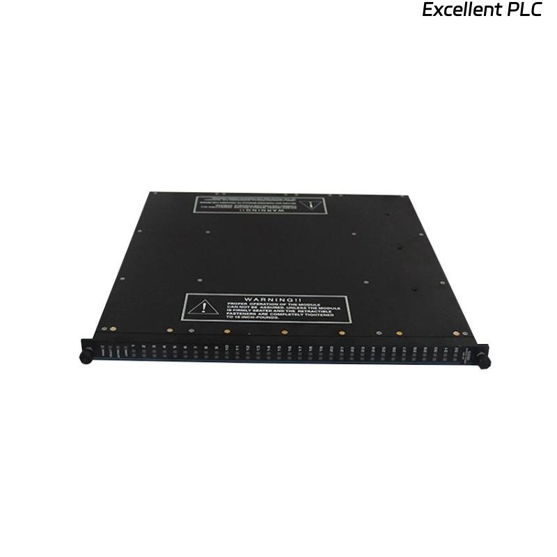
| Model | 7400063-100 |
| Type | Pulse Input Terminal Board |
| System | Triconex 3002 Series |
| Function | Interfaces pulse or frequency signals from field instruments |
| Typical Sources | Flow transmitters, speed pickups, turbine meters |
| Input Voltage Range | 0–24 VDC (typical pulse signals) |
| Mounting Type | DIN-rail or panel mounted adjacent to I/O chassis |
🧰 2. Pre-Installation Checklist
Before starting installation, confirm that all safety and compatibility conditions are met:
-
✅ System power OFF
-
✅ Static-safe workstation prepared (ESD protection)
-
✅ Verify part number and firmware compatibility with Tricon 3002 mainframe
-
✅ Ensure cabinet ambient temperature < 40 °C
-
✅ Field cables are labeled and pre-tested
⚠️ Note: Do not perform live wiring on pulse input circuits — these channels are sensitive to transient voltage spikes.
🔩 3. Mechanical Installation Procedure
-
Identify Mounting Location
Locate the designated terminal board position as per the wiring diagram.
The 7400063-100 typically sits next to the Pulse Input Module slot within the I/O rack. -
Secure the Board
Mount the terminal board onto the DIN rail or panel using the provided clamps.
Ensure mechanical stability — vibration can affect signal quality. -
Connect the Ribbon Cable
Attach the 34-pin ribbon connector between the terminal board and the Pulse Input Module.
Make sure the alignment notch matches the module port. -
Tighten Terminal Screws
All field signal cables should be securely fastened (recommended torque: 0.5–0.6 N·m).
⚡ 4. Electrical Wiring Guidelines
| Signal Type | Recommended Wiring | Notes |
|---|---|---|
| Pulse / Frequency (0–24 VDC) | Twisted pair shielded cable | Shield grounded at one end only |
| Common / Return | Single shared ground per channel group | Avoid daisy-chaining |
| Sensor Power | Separate fused 24 VDC supply | Prevents feedback noise |
💡 Tip: Keep pulse signal lines physically separated from high-current AC cables to reduce EMI coupling.
🧮 5. Verification and Testing
After installation, follow these steps to validate functionality:
-
Continuity Test — Verify each signal wire from field device to terminal point.
-
Voltage Check — Measure open-circuit voltage; should read within input spec range.
-
Module Communication Test — Using Tricon configuration software, confirm that the pulse input module recognizes all channels.
-
LED Status Review — Observe front panel LEDs:
-
RUN (Green): ON
-
FLT (Red): OFF
-
CH Indicators: Flashing with incoming pulse signals
-
-
Signal Simulation — If available, use a function generator to simulate a known pulse frequency (e.g., 10 Hz). Confirm module counts accurately.
🧠 6. Common Installation Mistakes (and How to Avoid Them)
| Mistake | Cause | Preventive Action |
|---|---|---|
| Module not detecting pulses | Reversed signal polarity | Check wiring diagram, correct polarity |
| Erratic readings | Poor shielding or shared return | Ground shield properly, separate returns |
| “No communication” alarm | Ribbon cable misaligned | Reseat 34-pin connector |
| Overheated terminal block | Excessive torque | Use correct torque tool and value |
🧾 7. Maintenance Recommendations
-
Inspect connections every 6 months for loosened terminals.
-
Clean contacts using isopropyl alcohol and lint-free swabs.
-
Keep spare terminal boards in ESD-safe packaging.
-
Document all modifications in system maintenance logs.
🧰 Remember: Pulse integrity depends on both clean signals and stable mechanical connections.
✅ Summary
The Triconex 3002 7400063-100 Pulse Input Terminal Board plays a vital role in ensuring precise signal transfer from field pulse devices into the Triconex logic system.
Proper mounting, shielding, and verification during installation prevent future communication errors and maintain long-term reliability of the entire TMR safety system.
“In pulse systems, accuracy begins at the terminal.”