

Recently, I encountered a Bently Nevada 2100-28-05-00-40-03-02 proximity sensor module that showed normal supply current but did not output any usable signal to the monitoring system. These modules are critical for eddy-current vibration monitoring, and such failures can lead to false alarms or system downtime. Here’s a detailed step-by-step field approach I followed.
Step 1: Safety and Initial Inspection
-
Ensure the machine and monitoring system are powered down before touching the sensor or module.
-
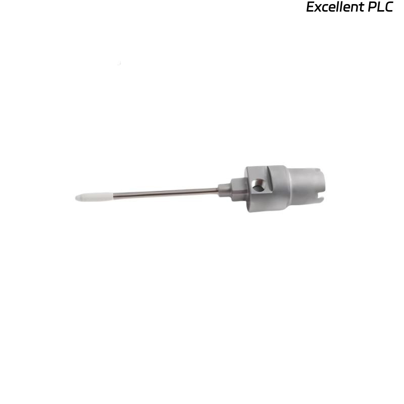
Verify the module part number: 2100-28-05-00-40-03-02.
-
Inspect for physical damage, bent pins, or moisture ingress.
-
Gather tools: multimeter, insulation tester, torque screwdriver, ESD wrist strap.
Field tip: Even if the module draws current, internal faults may prevent signal output.
Step 2: Verify Power Supply
-
Measure supply voltage at the module terminals.
-
Ensure voltage matches OEM specification (usually 24 VDC).
-
Check polarity — reversed supply can allow current but disable functionality.
Field insight: Modules often appear “alive” on current draw but fail internally due to reversed polarity or voltage spikes.
Step 3: Check Cabling and Connectors
-
Inspect the sensor cable for kinks, frays, or crushed sections.
-
Verify shield continuity from sensor tip to module.
-
Remove and inspect connectors for corrosion or bent pins.
-
Re-seat the connector to ensure firm mechanical and electrical contact.
Field tip: Loose shield or partially connected pins often cause “current without signal” symptoms.
Step 4: Sensor Element Test
-
If possible, test the prox sensor element separately using a calibrated test jig.
-
Confirm it produces expected AC signal when a target is moved within the sensing range.
-
If no signal is generated, the sensor element may be damaged and require replacement.
Step 5: Module Functional Verification
-
With sensor connected, measure output signal voltage or frequency at the module terminals.
-
Compare readings with known good reference.
-
If output remains zero despite normal current, the module’s internal circuitry may be faulty.
Field insight: A module drawing normal current but producing no output often indicates internal amplifier or PCB failure.
Step 6: Cleaning and Reassembly
-
Clean connector pins and cable ends with isopropyl alcohol.
-
Inspect the PCB for burn marks, corrosion, or water ingress.
-
Reassemble module and sensor, ensuring all pins and shields are properly seated.
Step 7: Replacement and Retest
-
If cleaning and re-seating do not restore functionality, replace the module with a spare from stock.
-
After replacement, test with the original sensor to confirm signal integrity.
-
Verify channel readings on the 3500 or PROXPAC system software.
Step 8: Common Causes for This Issue
-
Reversed or unstable supply voltage.
-
Loose or corroded connectors.
-
Damaged or internally shorted sensor element.
-
PCB fault inside module (amplifier failure).
-
Moisture ingress leading to intermittent shorts.
Step 9: Preventive Practices
-
Inspect connectors periodically and ensure proper sealing against moisture.
-
Label and document each module and sensor for future maintenance.
-
Use spare modules for critical machinery to minimize downtime.
-
Capture baseline readings after installation or repair to monitor long-term health.
Key Takeaways
-
Current draw alone does not indicate module functionality.
-
Proper inspection of power, connectors, and sensor element is essential.
-
Internal PCB failures are often only revealed during signal verification.
-
Field diligence, cleaning, and careful testing prevent unnecessary machine downtime.
“A module drawing current isn’t necessarily working — verify signal output carefully before assuming everything is fine.”