

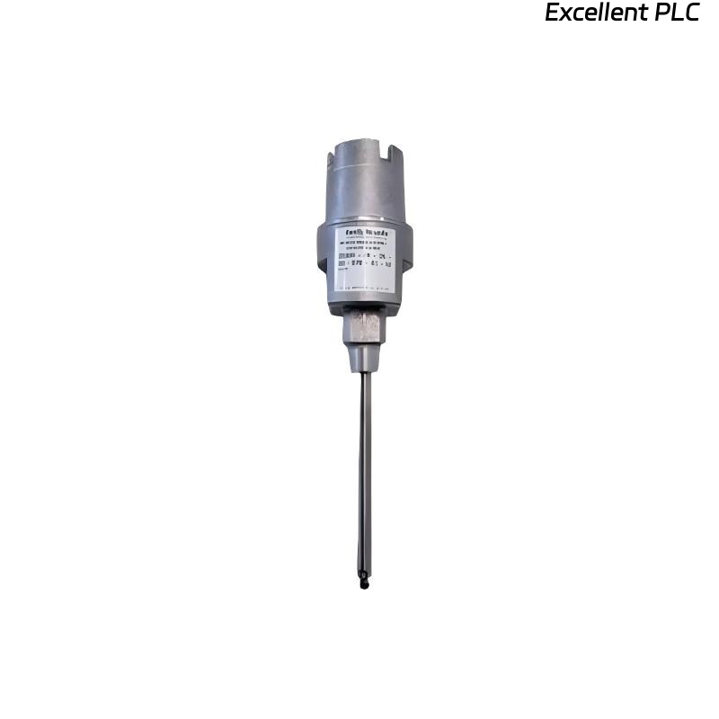
Recently, I worked on a Bently Nevada 24701-28-10-00-110-03-02 proximity sensor module installed on a turbine bearing housing. The module was reporting irregular readings, triggering false alarms and intermittent warnings. Here’s a detailed step-by-step approach I used to diagnose and resolve the issue in the field.
Step 1: Safety and Initial Assessment
-
Ensure the monitoring system and turbine are powered down before handling the sensor.
-
Confirm the module part number: 24701-28-10-00-110-03-02.
-
Gather tools: multimeter, oscilloscope, torque screwdriver, ESD wrist strap, and cleaning materials.
-
Inspect the module and sensor for visible damage or moisture ingress.
Field tip: Abnormal sensor readings can occur even if the module is powered and LEDs appear normal.
Step 2: Check Power and Grounding
-
Measure the supply voltage at the module terminals; confirm it matches OEM specifications (typically 24 VDC).
-
Check ground continuity between the module, sensor shield, and rack chassis.
-
Inspect for intermittent voltage drops by gently flexing the sensor cable.
Insight: Abnormal sensing often originates from unstable power or ground connections, even if current is drawn normally.
Step 3: Inspect Sensor Cable and Connector
-
Disconnect the sensor and inspect the cable for cuts, kinks, or crushed sections.
-
Check connectors for bent pins, corrosion, or loose mating.
-
Clean connector contacts with isopropyl alcohol if corrosion or oxidation is present.
-
Ensure the cable shield is continuous from sensor tip to module.
Field tip: A poor shield connection often causes erratic signals or false alarms.
Step 4: Verify Sensor Element Function
-
Using a test jig or nearby reference probe, check the sensor output by moving a metallic target within its sensing range.
-
Observe for smooth signal variation on a multimeter or oscilloscope.
-
If no signal or irregular behavior persists, the sensor element may be faulty and require replacement.
Step 5: Module Signal Verification
-
Reconnect the sensor and measure output at the module terminals.
-
Compare readings against baseline values or a known good channel.
-
Confirm that the module outputs a stable voltage or frequency signal.
Field insight: If the module shows stable power but erratic signal, the problem may be internal amplifier failure or PCB issues.
Step 6: Reassembly and Calibration
-
Reassemble the sensor and ensure correct alignment and air gap (per OEM specifications).
-
Tighten all connectors to recommended torque (~0.4–0.5 Nm).
-
Power up the system and verify LED indicators and software readings.
-
Perform a slow shaft rotation or target simulation to ensure proper sensor response.
Step 7: Common Causes of Abnormal Sensing
-
Loose or corroded connectors.
-
Broken or intermittent shield connection.
-
Damaged sensor element (coil or magnet).
-
Internal module PCB fault (amplifier or signal conditioning).
-
Incorrect air gap or misalignment.
Step 8: Preventive Measures
-
Document sensor serial number, location, and air gap settings.
-
Route cables away from high vibration or moisture areas.
-
Use strain relief to avoid stress on connector pins.
-
Schedule periodic inspection and baseline signal verification.
Key Field Takeaways
-
Abnormal proximity readings often originate from physical or electrical issues, not software.
-
Stepwise verification — power, ground, cable, connector, sensor, and module — ensures reliable diagnosis.
-
Preventive maintenance reduces the recurrence of sensing anomalies and system downtime.
“Even a small misalignment or loose shield can trick your monitoring system into false alarms — attention to every detail matters.”