

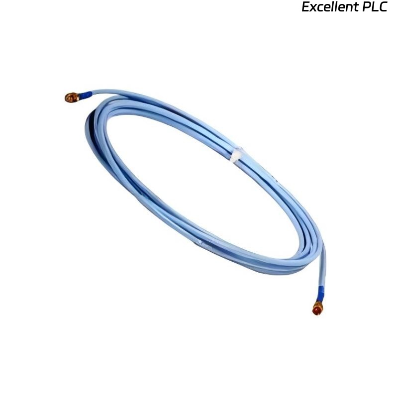
Recently, I encountered a Bently Nevada 330704-000-060-50-11-05 vibration/velocity sensor module in a compressor monitoring system showing connection anomalies. The module itself appeared powered, but signal data was intermittent or missing. Here’s a detailed, field-tested step-by-step approach I followed to identify and resolve the issue.
Step 1: Safety and Initial Checks
-
Ensure the monitoring system and machine are powered down before inspecting sensors or modules.
-
Confirm the module part number: 330704-000-060-50-11-05.
-
Gather tools: multimeter, oscilloscope (if available), torque screwdriver, ESD wrist strap, and cleaning cloths.
Field tip: Powering up during inspection can risk short circuits or damage the module.
Step 2: Visual Inspection
-
Check the module and sensor for physical damage, loose connectors, or corrosion.
-
Inspect the sensor cable for kinks, cuts, or crushed areas.
-
Verify that connectors are fully seated into the module terminal block or rack.
Field insight: Most connection issues arise from loose pins, bent terminals, or moisture ingress.
Step 3: Verify Power and Ground
-
Measure the supply voltage at the module terminals. Ensure it matches OEM specifications (typically 24 VDC).
-
Confirm ground continuity between the module, sensor, and system chassis.
-
Check for intermittent voltage drops while gently flexing the cable.
Field tip: A module may appear powered, but intermittent grounding or loose power wires can cause connection anomalies.
Step 4: Signal Path Verification
-
Use a multimeter or oscilloscope to measure sensor output signal at the module input.
-
For velocity sensors, check that the signal amplitude varies when the shaft or probe is moved slightly.
-
Compare readings with a known good sensor or channel to confirm correct range.
Field insight: If no signal is detected despite proper power, the problem may be sensor element failure or internal module fault.
Step 5: Connector Cleaning and Reassembly
-
Disconnect and inspect all connectors.
-
Clean contacts with isopropyl alcohol or approved electronic contact cleaner.
-
Verify that pins are straight and fully seated when reconnecting.
-
Maintain shield continuity for all sensor cables.
Field tip: Connector corrosion is a surprisingly common source of intermittent vibration readings.
Step 6: Module Functional Testing
-
Power up the module after cleaning and reassembly.
-
Observe the module LED indicators for power and fault status.
-
Use the monitoring system software to verify that channel readings are now stable.
-
Slowly rotate the shaft or simulate vibration to ensure the module responds correctly.
Field tip: Test one channel at a time to isolate potential issues.
Step 7: Common Causes of Connection Anomalies
-
Loose or improperly seated connectors.
-
Moisture ingress inside cable or connector.
-
Broken shield or intermittent ground connection.
-
Damaged sensor element (coil or magnet).
-
Internal module circuitry fault.
Step 8: Preventive Measures
-
Ensure all connectors are properly torqued and fully seated.
-
Route sensor cables away from heat, vibration, or moisture.
-
Periodically inspect and clean connectors as part of preventive maintenance.
-
Document sensor location, module channel, and wiring for troubleshooting history.
Field Takeaways
-
Connection anomalies often originate from physical issues rather than software faults.
-
Methodical inspection — power, wiring, shielding, and sensor element — is key to restoring reliable readings.
-
Preventive maintenance, including cleaning and documentation, reduces the likelihood of recurring faults.
“In vibration monitoring, an unstable connection can be more damaging than a failed sensor — attention to cables and connectors ensures reliable machine protection.”