

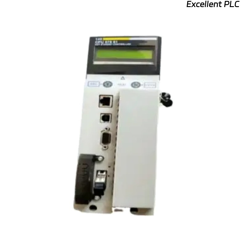
A few weeks ago, we had a situation in our production facility with a Schneider 140XTS33200 I/O connector. The small display on the module had stopped working entirely—no backlight, no numbers, nothing. The PLC was still functioning and controlling the I/O, but without the display, we couldn’t see the status of the inputs and outputs or any diagnostic information. I want to share exactly how I approached this problem, step by step, based on my on-site experience.
Step 1: Initial Safety and Power Down
The first step was to ensure the panel was completely powered down. Even though this is a low-power I/O connector, it’s essential to disconnect all power and follow standard lockout procedures. Safety always comes first. Once the panel was safe to work on, I removed the module from its slot in the rack.
Step 2: Physical Inspection
I examined the display carefully:
-
Checked for visible cracks or physical damage.
-
Verified the connector pins for any bending or corrosion.
-
Looked for signs of moisture or dust accumulation around the display and ribbon connector.
Everything looked fine externally, which suggested that the problem might be internal, but I did not want to jump to conclusions before checking all simple causes.
Step 3: Check Ribbon Cable and Connectors
One common cause of display failure is a loose or dirty ribbon cable:
-
I carefully unplugged the ribbon cable connecting the display to the module circuit.
-
Cleaned the connector pins with isopropyl alcohol.
-
Reinserted the cable firmly, ensuring it was seated evenly.
After powering the system on, the display still did not show anything. This confirmed that the issue was not just a loose connector.
Step 4: Electrical Diagnostics
I then measured the voltage supply to the display using a multimeter:
-
Verified that the module was receiving proper 5 VDC supply for the display.
-
Checked continuity of the ribbon cable again to rule out hidden wiring breaks.
The voltage readings were normal, indicating that the module was receiving power correctly. At this point, the display itself or its internal driver circuitry seemed to be the culprit.
Step 5: Module Replacement
Given the delicacy of the integrated display, attempting an internal repair in the field would have been risky and time-consuming. Based on experience with these modules, the most efficient and safe approach is to replace the entire 140XTS33200 connector module:
-
Remove the faulty module completely from the rack.
-
Prepare a new or tested spare 140XTS33200 module.
-
Install it in the same slot carefully, making sure all backplane contacts align properly.
-
Reconnect all control wiring, I/O lines, and ribbon connectors.
Step 6: Power-Up and Verification
After reinstalling the new module:
-
Power was restored gradually.
-
The display powered on immediately, showing all segments correctly.
-
I checked I/O status, verified inputs and outputs, and ran basic test routines from the PLC.
-
Monitored the module for a few minutes to ensure no intermittent issues occurred.
Everything worked as expected, and the production line resumed normal operation.
Step 7: Lessons Learned
From this incident, I noted several practical lessons for the future:
-
Always check ribbon connectors and small cabling first—these are surprisingly common causes of display failure.
-
Confirm that the module receives the correct supply voltage before assuming internal failure.
-
For integrated display failures, replacement is usually safer and faster than attempting in-field repair.
-
Document serial numbers and installation dates of modules, as older batches sometimes have recurring display issues.
-
Test the new module gradually and verify all I/O to prevent new faults from unnoticed wiring problems.
This case highlights that even minor components like small I/O displays can impact operations significantly. By carefully diagnosing, checking simple things first, and then performing a structured replacement, the issue was resolved quickly and safely.