

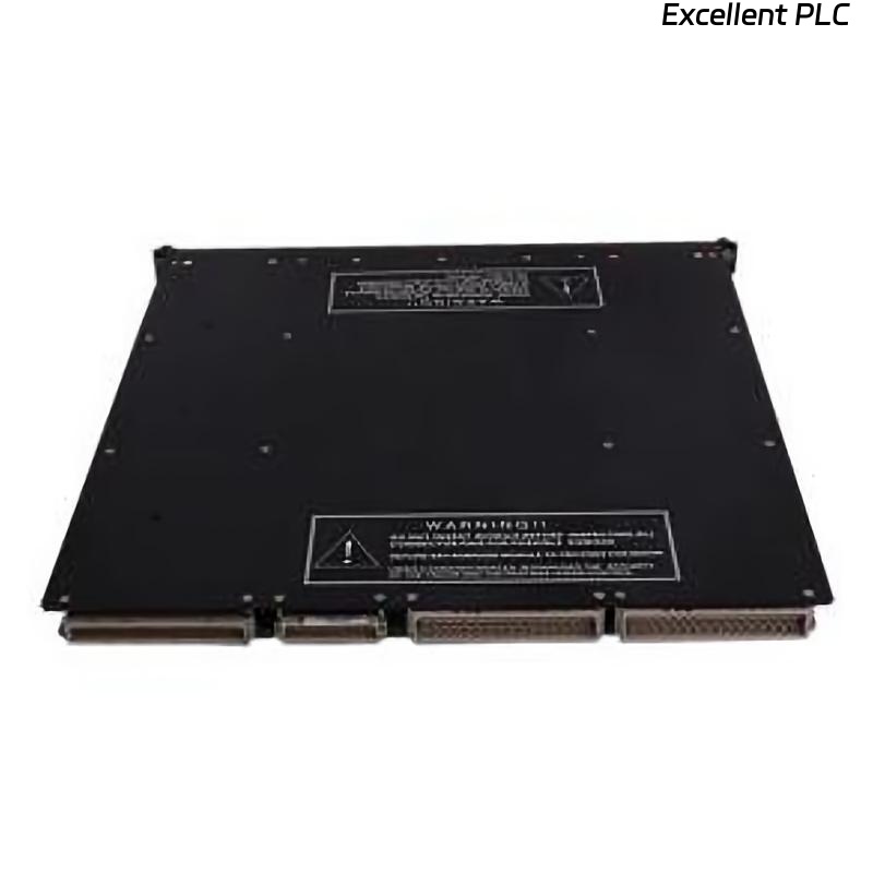
The Triconex 3000604-100 Digital Input (DI) module is designed to monitor field devices such as switches, sensors, and safety interlocks in a TMR system. If it shows no input signals, the issue could originate from wiring, field devices, module electronics, or backplane communication.
Start with Power Verification
Before diving into electronics, confirm that the module is receiving proper supply voltages. Check the +5 V and +24 V rails on the module terminals. Many field engineers point out:
“If the module doesn’t see stable power, you won’t see a single valid input.”
Also, inspect the status LEDs. A completely unlit DI module often indicates power or backplane issues rather than failed inputs.
Inspect Field Wiring and Connections
The next step is to verify the wiring from field devices:
-
Make sure all switches, sensors, and signal sources are energized according to design.
-
Check terminal blocks for loose or corroded screws.
-
Use a multimeter to confirm continuity from the field device to the module input.
Field tip: Labeling wires and following the wiring diagram prevents accidental misconnection.
Examine the Backplane and Module Seating
Remove the module carefully and inspect the backplane connector:
-
Dust, oxidation, or bent pins can block signal recognition.
-
Ensure the module slides in smoothly and fully engages with the rack.
-
Neighboring modules may affect the DI module if the backplane is damaged.
Engineer note: “Sometimes the module is fine, but a dirty slot gives the appearance of a dead DI module.”
Module Electronics Check
If power and wiring are good:
-
Look for damaged ICs, burnt resistors, or swollen capacitors on the DI module PCB.
-
Test input channels individually with a known signal to confirm whether the module detects it.
-
Replace any obviously failed components if skilled in high-reliability electronics repair.
Pro advice: Only attempt component-level repairs if you have experience; otherwise, use a known-good replacement.
Confirm Communication with the System
-
Use Triconex diagnostics to verify that the module is recognized by the CPU.
-
In TMR systems, a DI module may fail to report signals if redundancy paths or configuration are mismatched.
Observation from the field: “Some ‘no signal’ issues are actually software recognition problems, not hardware failures.”
Post-Repair Testing
Once suspected faults are corrected:
-
Reinstall the module and reconnect field devices.
-
Simulate input signals one by one and confirm proper detection in the diagnostics interface.
-
Run a short operational test to ensure stable recognition before returning to production.
Field engineers often say: “Test everything twice—intermittent inputs can ruin system reliability.”
Practical Takeaways from Maintenance Teams
-
Start with power and backplane before assuming the module is dead.
-
Check field wiring carefully; loose or swapped connections are common.
-
Inspect module electronics only after eliminating simpler causes.
-
Verify system recognition to rule out configuration or redundancy issues.
-
Always perform a full functional test before production restart.
Experience note: “In TMR safety systems, no single check is enough—methodical verification prevents accidents.”