

The 1771-OAN is a 32-channel AC output module for PLC-5 systems. It switches AC loads such as motors, solenoids, and indicators. Proper wiring is essential to ensure safe operation and reliable output control.
Step 1: Safety First
Always power down the chassis and field circuits before wiring. AC outputs can be lethal, and working live may damage the module or cause injury.
Step 2: Identify Terminals
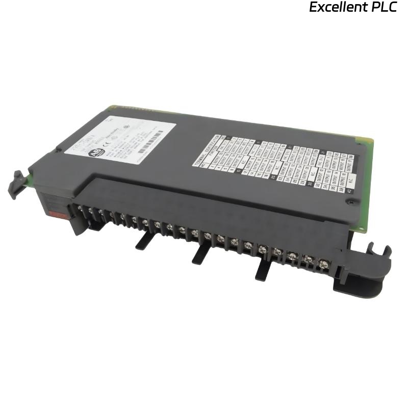
The 1771-OAN module has 32 output terminals arranged in two rows. Each output has:
-
Line (L) terminal – connect to AC supply phase
-
Load terminal – connect to the device being switched
-
Common (COM) – typically shared for groups of outputs
Consult the module label for exact numbering.
Step 3: Wiring Procedure
-
Strip each wire to 6–8 mm.
-
Connect the AC phase to each output line terminal.
-
Connect the device (motor, lamp, etc.) to the corresponding output terminal.
-
Ensure common connections are properly wired according to the module group.
-
Tighten screws securely but avoid over-torquing to prevent terminal damage.
Field tip: Label each wire according to output channel number for easier troubleshooting and future maintenance.
Step 4: Verification
-
Double-check all connections for correct polarity and secure contacts.
-
Power up the PLC and observe the module LEDs; they indicate output status.
-
Test each output with a small load to verify correct switching.
References:
-
Rockwell Automation. 1771-OAN AC Output Module User Manual, 2019.
-
Rockwell Automation. PLC-5 Wiring Guidelines, 2018.