

1️⃣ Background
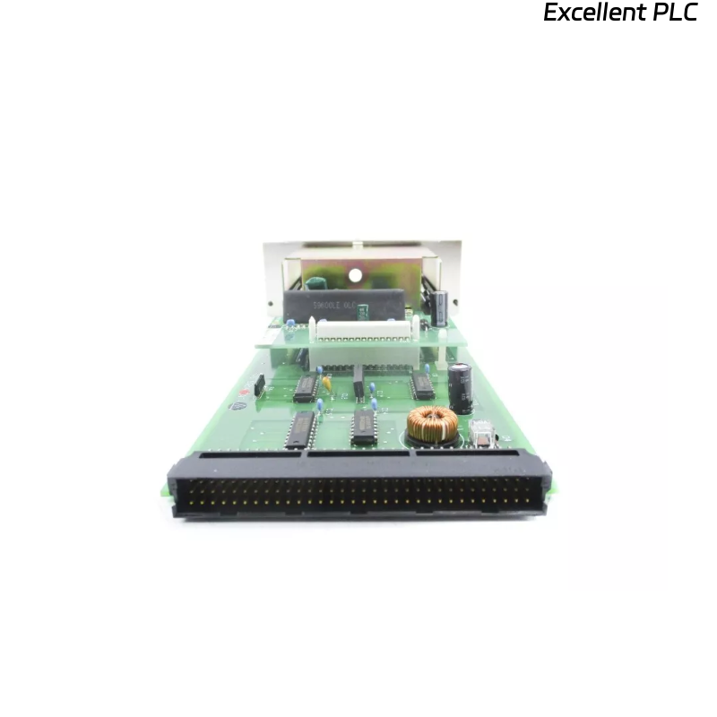
The Yokogawa AIP552 Bus Converter Module is a key component in the CENTUM CS3000 / VP distributed control system.
It functions as the interface between system buses — typically linking control stations, I/O modules, and communication networks.
A distinct burnt or scorched smell from the AIP552 after startup or operation is an immediate warning sign.
It usually indicates component overheating, power supply failure, or circuit board damage.
Immediate inspection is required to prevent further equipment loss or network interruption.
2️⃣ Initial Symptoms and Observations
Common signs observed during the fault:
-
Burnt odor near the module housing or ventilation area.
-
PWR or RUN LEDs off, or flickering irregularly.
-
ERR LED remains red or flashes continuously.
-
Adjacent modules on the rack still function normally.
-
In some cases, a temporary smoke trace or melting plastic smell may be detected.
⚠️ Warning: If smoke or strong odor persists, power down the entire rack immediately. Continuing operation may cause further PCB damage.
3️⃣ Primary Causes (Based on Field Experience)
| Root Cause | Description | Common Area Affected |
|---|---|---|
| DC-DC converter failure | Internal power circuit shorted or overheated | Power section near connector |
| Electrolytic capacitor leakage | Aged capacitor vented and leaked electrolyte | Secondary voltage filtering area |
| Backplane overcurrent | Shorted I/O pins or misaligned insertion | Connector or trace near backplane |
| Dust accumulation | Conductive carbonized dust creating micro-arcs | Ventilation holes, PCB underside |
| Excessive ambient heat | Rack temperature > 55°C causing thermal stress | All components, especially regulators |
4️⃣ Step-by-Step Troubleshooting
Step 1 — Power Isolation and Visual Inspection
-
Turn off system power immediately.
-
Wait 5–10 minutes for capacitors to discharge.
-
Remove the AIP552 module carefully.
-
Check for:
-
Burn marks or darkened PCB areas.
-
Deformed or melted components.
-
Smell source location (front power input vs rear board).
-
🔧 Tip: The burnt smell often originates from the DC converter IC or power transistor area near the lower right of the board.
Step 2 — Measure Power Circuit Continuity
Using a multimeter:
-
Measure between the 24V input and GND.
-
If near 0 Ω, the power input stage is shorted.
-
-
Check diode polarity and capacitor integrity (for bulging tops or leaks).
-
Verify no short across the secondary voltage rails (5V, 3.3V).
If abnormal readings are found, do not attempt power reapplication — the fault must be isolated first.
Step 3 — Inspect Backplane and Connector
-
Look at the rack’s backplane connector for heat marks or melted plastic.
-
Clean contacts with dry compressed air or contact cleaner.
-
If discoloration is present on pins → replace both connector and module.
-
Ensure no metal fragments or conductive dust remain.
Step 4 — Analyze Surrounding Conditions
-
Measure ambient temperature inside the cabinet.
-
Confirm ventilation fans are operating.
-
Check other modules for abnormal heat buildup.
-
If multiple modules show elevated temperature, verify rack power supply ripple and output voltage stability.
🧠 Field Note: Some AIP552 units overheat when operating at >27 VDC continuously — even within the nominal 24V range — due to internal regulator tolerance.
Step 5 — Replacement and Verification
-
Replace the AIP552 with a known-good spare of the same firmware and hardware revision.
-
Re-seat properly into the same slot.
-
Power on and monitor LED indicators for 15 minutes.
-
PWR: Steady green
-
RUN: Blinking green
-
ERR: Off
-
-
If all status LEDs are normal and no odor persists → previous module confirmed defective.
If replacement also shows heat or failure, investigate rack wiring and power noise.
5️⃣ Preventive Maintenance Recommendations
| Task | Frequency | Purpose |
|---|---|---|
| Clean air filters & fans | Every 3–6 months | Ensure cooling efficiency |
| Check cabinet ambient temperature | Monthly | Prevent thermal stress |
| Inspect backplane contacts | Annually | Avoid oxidation and arcing |
| Replace aging electrolytic capacitors | Every 5 years | Maintain voltage stability |
| Verify power supply ripple | Semi-annually | Prevent DC converter stress |
6️⃣ Technical Insight
According to field repair statistics, over 60% of AIP552 modules showing burnt smell were traced to internal DC/DC converter or capacitor failures caused by:
-
Prolonged exposure to high temperature,
-
Aging components (>8 years),
-
Or contaminated airflow channels.
These cases rarely originate from software or configuration errors — they are purely hardware-related thermal issues.
7️⃣ Summary of Actions
When the Yokogawa AIP552 Bus Converter Module emits a burnt odor:
-
Immediately power off the system.
-
Inspect the board visually and electrically.
-
Check for short circuits in power input or DC-DC stage.
-
Verify cabinet cooling and voltage conditions.
-
Replace and retest with a verified unit.
Proper preventive maintenance and timely replacement of aging components can prevent recurrence.